Hi,
Thanks for the reply,
Hmmm Maybe I was too cryptic when I said no input...sorry.
I meant with no audio input....amp powered...ignoring the load. Would it then switch at output filter resonance or .....explode?
I do hope you give "The Book" further consideration, I'd buy it.
Nicer retirement fund for you than an internal only version would provide as well.
Take care.
Also wanted to ask Jan Peter in my earlier post why he's marketing his UCD modules as Sub amps? I'm waiting for the 400W version for a 3 way set up..what's your cut off on them?
Thanks alot.
Chris
Ah oh. The amp likes to see a definite input source. The simple one from the patent is OK with a few hundred pf to ground (positive input is high impedance), but the newer ones more or less presume an op amp preamp always connected.classd4sure said:Hmmm Maybe I was too cryptic when I said no input...sorry.
I meant with no audio input....amp powered...ignoring the load. Would it then switch at output filter resonance or .....explode?
Retirement? How old do you think I am? (Hint: 2^5-1)
Cheers,
Bruno
Hi Bruno,
Philips semiconductor division has a new class D power comparator TDA9839 . It´s main advantage is a very high common mode range of logic inputs, so it can be used for split or single supply amplifiers. I think it could be of great help to DIYers with minimum switching stage design experience for implementig either SODA or UCD type amplifier. If you have any first hand experience with this chip, I would be interested in your comment.
Best regards,
Jaka Racman
It's got another advantage, which is a very short dead time. They call it zero, but 10ns is not muchJaka Racman said:Philips semiconductor division has a new class D power comparator TDA9839 . It´s main advantage is a very high common mode range of logic inputs, so it can be used for split or single supply amplifiers. I think it could be of great help to DIYers with minimum switching stage design experience for implementig either SODA or UCD type amplifier. If you have any first hand experience with this chip, I would be interested in your comment.
")
Some disadvantages are the noise of the CMOS inputs and a serious problem of crosstalk. Or, let me put it this way: the crosstalk on the chip is amazingly low, but the package and pcb layout does not allow the user to take full advantage of this. So, if you want to make a stereo amp with it, you'll have to add external comparators even though the input is in itself quite good.
A full bridge, again with an external comparator (in order to force synchronicity) has been demonstrated with very nice results.
So, if the chip came in mono units it would make an excellent vehicle for all sorts of self-oscillating amps but as a stereo chip its application lies elsewhere.
Cheers,
Bruno
Ahhhhhh, a provisional data-sheet, finally !!!!
I was already going to think that this is just vapourware !!!!!
This would indeed be an interesting thingie, making development of class-d amps much easier.
From the functional description (specially the comparator input) this should be usable for all sorts of class-d topologies (self oscillating PWM, carrier-based PWM......).
Now if it would be available in small quantities at an interesting price .........
Regards
Charles
Hi Bruno,
thanks for the report. I was thinking of paralleling outputs in split supply version and also using of your discrete comparator anyway. At least external comparator allows for some creativity . Otherwise speculation would go into direction whether is is better to orient feedback resistor north to south or east to west.
Best regards,
Jaka Racman
thanks for the report. I was thinking of paralleling outputs in split supply version and also using of your discrete comparator anyway. At least external comparator allows for some creativity
. Otherwise speculation would go into direction whether is is better to orient feedback resistor north to south or east to west.Best regards,
Jaka Racman
Apparently you have a very low impedance to drive...Jaka Racman said:I was thinking of paralleling outputs in split supply version
A nice way of parallelling without risking trouble due to possible propagation delay differences is to give each half its own output coil and parallel at the output cap. It makes the currents on the layout easier to trace as well.
Jan Peter,
Many thanks for taking the time to run the THD+N measurement for me.
Despite hardly ever using the AP, I keep it as it’s the industry standard - for this reason my clients prefer to see AP plots to the UPD.
Have I missed a way to set the generator output level without direct numeric entry?
John
Many thanks for taking the time to run the THD+N measurement for me.
Despite hardly ever using the AP, I keep it as it’s the industry standard - for this reason my clients prefer to see AP plots to the UPD.
Have I missed a way to set the generator output level without direct numeric entry?
John
If there were one. This is one of the few gripes I've got with the device. The old DOS software reacted to the plus and minus keys, but you know, in these windows times, why use anything more practical than a mouse?JohnW said:Have I missed a way to set the generator output level without direct numeric entry?

Bruno
I think they where aware of the possibility and I am just as surprised as you that they didn´t claim it as well. The reason that I think they where aware of using the output filter as modulator is that they do exactly that in their previous patent (WO 02/25357 from 2000) in which they claim a self oscillating current loop with an outer voltage loop. They actually also describes using the output voltage with a zero hysteresis comparator as previous art (line 15). Measuring the current through the load (not including the capacitor current) and using it with a zero hysteresis comparator gives the exact same function as ucd but with a current generator frequency response. Instead of using the output voltage for modulation they use an attenuated part of the output voltage and feed it back to the comparator.
I understand that this sounds a bit strange but what I am trying to say is that one of the criterions for patentability is that there must be a "technological height" of the patent application. Simply replacing a low pass filter with another doesn´t do it for me when it comes to patentability. A circuit doesn´t have to be patented before in order to be refused but could then be public domain.
Icepower: They were obviously *not* aware of the possibility of producing stable self-oscillation using the post-filter signal only. Otherwise they would have made sure that the patent at least cover this option. No patent applicant knowingly leaves open such an alternative option.
I think they where aware of the possibility and I am just as surprised as you that they didn´t claim it as well. The reason that I think they where aware of using the output filter as modulator is that they do exactly that in their previous patent (WO 02/25357 from 2000) in which they claim a self oscillating current loop with an outer voltage loop. They actually also describes using the output voltage with a zero hysteresis comparator as previous art (line 15). Measuring the current through the load (not including the capacitor current) and using it with a zero hysteresis comparator gives the exact same function as ucd but with a current generator frequency response. Instead of using the output voltage for modulation they use an attenuated part of the output voltage and feed it back to the comparator.
Reading the last paragraph of your post, I find it interesting that you are trying to knock over the UcD patent (using other patents) because you feel it shouldn't have been patented and hence be free for all. I take this as a sign of your appreciation of its usefulness. Of course, it is this usefulness that led my employer to patenting it.
I understand that this sounds a bit strange but what I am trying to say is that one of the criterions for patentability is that there must be a "technological height" of the patent application. Simply replacing a low pass filter with another doesn´t do it for me when it comes to patentability. A circuit doesn´t have to be patented before in order to be refused but could then be public domain.
Hi,
First, may I say thanks for your words of encouragement during my “Labour”
Just a quick update (maybe I should start a new thread?)
I spent the week constructing the PCB – jumping many hurdles – (thanks Flint for the COG’s that appear to be X7R’s, at least I think - dark brown dielectric not Salmon pink)
Construct only half side of HBridge – but first results seem promising, still away to go before a fully optimise design, constantly running into the limits of the UPD05 (long given up on the AP).
Biggest problem I now have is thermal / 1/f noise at lower power levels.
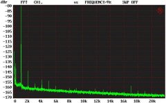
Below's an FFT of 1W 8R Single Ended, 0dB referenced to 100W, THD 0.00008% SE. Harmonics are the product of the R&S internal Generator.
That fact that there are basically no harmonics at lower powers bodes well for sound quality (Harmonics visible appear to be due to the R&S internal Gen).
Notice the gradual sloping of the noise floor – I believe indicating thermal noise, but further research is required. The FFT’s between the R&S generator and Amp output are identical – apart from the amps higher noise floor towards DC
But still very early days….
John
FFT of 1W 8R Single Ended, 0dB referenced to 100W, THD 0.00008% SE
First, may I say thanks for your words of encouragement during my “Labour”
Just a quick update (maybe I should start a new thread?)
I spent the week constructing the PCB – jumping many hurdles – (thanks Flint for the COG’s that appear to be X7R’s, at least I think - dark brown dielectric not Salmon pink)
Construct only half side of HBridge – but first results seem promising, still away to go before a fully optimise design, constantly running into the limits of the UPD05 (long given up on the AP).
Biggest problem I now have is thermal / 1/f noise at lower power levels.
Below's an FFT of 1W 8R Single Ended, 0dB referenced to 100W, THD 0.00008% SE. Harmonics are the product of the R&S internal Generator.
That fact that there are basically no harmonics at lower powers bodes well for sound quality (Harmonics visible appear to be due to the R&S internal Gen).
Notice the gradual sloping of the noise floor – I believe indicating thermal noise, but further research is required. The FFT’s between the R&S generator and Amp output are identical – apart from the amps higher noise floor towards DC
But still very early days….
John
FFT of 1W 8R Single Ended, 0dB referenced to 100W, THD 0.00008% SE
Attachments
19 and 20KHz two tine IMD test results....
Hi John,
Can post the 19 and 20Khz two tone test results for us at say 100W into 8 Ohms.
Bruno / Jan Peter,
Did you have any 19 / 20K two tone IMD test for the UCD at the same power (John asked about this back along i think...?).
Cheers
Sheriff
Hi John,
Can post the 19 and 20Khz two tone test results for us at say 100W into 8 Ohms.
Bruno / Jan Peter,
Did you have any 19 / 20K two tone IMD test for the UCD at the same power (John asked about this back along i think...?).
Cheers
Sheriff
Hi,
Yes, I thought if the positive input were tied and couldn't float with no input signal present during power up, one of the power fets would hit one of the rails, and the feedback from the rc loop sets Fres constant so it can't latch up, no start up circuit required to get it going either, nice.
I guess 16 or 31, what, no book yet?
Cheers
Chris
Ah oh. The amp likes to see a definite input source. The simple one from the patent is OK with a few hundred pf to ground (positive input is high impedance), but the newer ones more or less presume an op amp preamp always connected.
Yes, I thought if the positive input were tied and couldn't float with no input signal present during power up, one of the power fets would hit one of the rails, and the feedback from the rc loop sets Fres constant so it can't latch up, no start up circuit required to get it going either, nice.
I guess 16 or 31, what, no book yet?
Cheers
Chris
John,
Looks your are the winner for the lowest THD!
I did not yet understand your total setup, can you probably tell it again?
Perhaps some small block schematic will makes it easier to understand.
Regards,
Jan-Peter
www.hypex.nl
Looks your are the winner for the lowest THD!
I did not yet understand your total setup, can you probably tell it again?
Perhaps some small block schematic will makes it easier to understand.
Regards,
Jan-Peter
www.hypex.nl
You are hereby made aware of the fact that in this drawing the output filter is taken to be an integral part of the load. The output voltage referred to is the pre-filter (switch) output. It is desirable, based on this and previous experiences quoting patents, that such documents be read with rather more rigour than mere perusal, especially if it is one's desire to contest another patent.Pabo said:They actually also describes using the output voltage with a zero hysteresis comparator as previous art (line 15).
Notice is taken of the flexible use of the word exact.Pabo said:Measuring the current through the load (not including the capacitor current) and using it with a zero hysteresis comparator gives the exact same function as ucd but with a current generator frequency response. Instead of using the output voltage for modulation they use an attenuated part of the output voltage and feed it back to the comparator.
Reasoning in simplified terms such as "attenuated output" will not get you far in the analysis either of UcD or COM.
I am at liberty to refer you to an earlier discussion in this thread where I point out the difference between "simple" and "obvious". Especially post factum, these two qualities are often confused.Pabo said:what I am trying to say is that one of the criterions for patentability is that there must be a "technological height" of the patent application. Simply replacing a low pass filter with another doesn´t do it for me when it comes to patentability. A circuit doesn´t have to be patented before in order to be refused but could then be public domain.
In any case, I have not quite been convinced that my analysis of your motifs is wanting. Your sustained attack on the UcD patent is still taken as a compliment.
Bruno Putzeys
QUOTE]You are hereby made aware of the fact that in this drawing the output filter is taken to be an integral part of the load. The output voltage referred to is the pre-filter (switch) output. It is desirable, based on this and previous experiences quoting patents, that such documents be read with rather more rigour than mere perusal, especially if it is one's desire to contest another patent.[/QUOTE]
So you are hereby saying that if I where to phase modulate the amplifier with the current flowing through the actual load, I would not be in conflict with any patent? In that case I hereby state it as public domain
Of course you should take it as a compliment. Your design is extremely simple and performs astonishing results. It is a joy to see what you can perform with and without an additional voltage loop.
Finally I must add that I have some difficulties in reading patent applications as they write them in a somewhat difficult way. You argue very well so I assume that I will not have caused you any problems.
QUOTE]You are hereby made aware of the fact that in this drawing the output filter is taken to be an integral part of the load. The output voltage referred to is the pre-filter (switch) output. It is desirable, based on this and previous experiences quoting patents, that such documents be read with rather more rigour than mere perusal, especially if it is one's desire to contest another patent.[/QUOTE]
So you are hereby saying that if I where to phase modulate the amplifier with the current flowing through the actual load, I would not be in conflict with any patent? In that case I hereby state it as public domain
In any case, I have not quite been convinced that my analysis of your motifs is wanting. Your sustained attack on the UcD patent is still taken as a compliment.
Of course you should take it as a compliment. Your design is extremely simple and performs astonishing results. It is a joy to see what you can perform with and without an additional voltage loop.
Finally I must add that I have some difficulties in reading patent applications as they write them in a somewhat difficult way. You argue very well so I assume that I will not have caused you any problems.
That's cool of youPabo said:(...) that if I where to phase modulate the amplifier with the current flowing through the actual load, I would not be in conflict with any patent? In that case I hereby state it as public domain
I haven't thought it through but maybe it's a recipe for a good class D current source. These things are quite interesting for positioning equipment using linear actuators. Having a large bandwidth would permit greater throughputs in e.g. wafer steppers.
- Home
- Amplifiers
- Class D
- Which chip and whatever happened to Mueta and UCD?