
MEGA-amp said:I've think I've found a better idea.
Certainly not my idea, but I'm certain mine will come out just as nice. I've seen some threads lately where water cooling gets brought up, I think this would be the best way to implement it cheaply, and provide serious cooling.
Gyuri said:Only not the copper would be in a golden price.
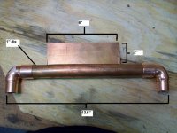
My implementation: 2 pcs - 1/4" thick, 3"x4", 1"dia copper pipe. each channel (F5) will get its own plate. Copper cost: 66USD. Not terribly bad, considering that big bad heat sinks can cost an arm and leg.
its someone else's design and the pics were lifted. I'll use any combination of a chop saw, hack saw, jig saw, table saw, sawzall....whatever works. The only problem I envision is; the notch is 1/4" (6.4mm) wide, and there aren't many metal cutting blades with that thickness. Dremel might be the way to go here.....
Grey, or the Thermal Guru....Jacco.... you around?
-John
Grey, or the Thermal Guru....Jacco.... you around?
-John
You underestimate the power of the Force!
...er...sorry...
You underestimate the power of Water Cooling!
It's not necessary to go to such lengths to get the heat to transfer. (Jeez! Dimples?) However, be that as it may, yes, it will be even more efficient than a simple butt joint like I use. Just be sure you've got that slot soldered shut. Considering that the slip joints are designed for something like a 1/2" deep continuous-coverage solder joint and judging from the pictures, you've got just a relatively thin solder joint at the seam with little or no copper to back it up, there's a potential for trouble in the slot idea. Also remember that you'll subject the assembly to mechanical stress while mounting the devices, etc.
Assuming that I were to pursue the slot idea, I'd probably use a Dremel or a band saw with the pipe stood on end, then use a file to perfect the edges so as to get as clean a fit as possible. And lotsa solder.
Grey
MEGA-amp said:pics were lifted.
...from another site . The guy that made those was using it to cool a PS for an over-clocked PC. He made a jig, then a couple passes through a table saw......easy.
")
The closest i've been to a Guru was on top of one in my younger degenerate days. (i better skip the details on that spiritual leader lady because i've just pledged to behave on the PL forum)
Cool stuff.
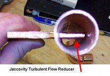
The flange insert will make it operate as a flow control valve, means a large pressure drop.
Downstream, the flow will become turbulent enough due to the channel division, with a flat frontal surface of the flange on the entry side as on the picture you can expect a sizeable dead fluid flow area on both sides of the flange tip.
Think of a ship with a square shaped bow, and how the water will flow around it.
Best to file the entry and exit side of the flange in a V shape for the highest interaction between the water and the flange, plus gradual pressure variations.
Cool stuff.
The flange insert will make it operate as a flow control valve, means a large pressure drop.
Downstream, the flow will become turbulent enough due to the channel division, with a flat frontal surface of the flange on the entry side as on the picture you can expect a sizeable dead fluid flow area on both sides of the flange tip.
Think of a ship with a square shaped bow, and how the water will flow around it.
Best to file the entry and exit side of the flange in a V shape for the highest interaction between the water and the flange, plus gradual pressure variations.
jacco vermeulen said:Looking forward, don't use 90 degree fittings if you have 135 angle types.
I am assuming to reduce noise created by water flowing? I will be putting a flow control ball valve to adjust water flow from 0.5-3gpm, would it be even noticeable?
Basic fluid dynamics, water speed at the inside corner of a 90 degree angle would be zero.
You try going full stop at a traffic crossing, and at the same time accelerating in a perpendicular direction.
For laminar flow, fluid speed distribution of a round cross section is bell shaped, zero right at the walls and reaches the max in the center.
A 90 degree angle has a really uggy flow speed distribution, speed variations translates to pressure variations.
At high flow speeds you'd have a whistle, at low speeds an additional and unnecessary power loss.
3gpm in a 1/2" pipe is ~8ft/s (3/8" inside diameter), pretty heavy.
(because of the dead flow area at the inside corner of 90 degree angles, they're off-limits in sewer systems, a sewer in your home would clogg up within months at that spot)
Oh, fer cryin' out loud!
Are you guys tryin' to find something to obsess about or are you just doin' this to be contrary?
Read my lips: No noise. None. Zip. Nada.
Unless you expect to have some truly prodigious flow rates, it's a non-issue. I don't remember offhand what my pump does (it's in my cooling thread--if you're interested, you can look there), but I think it was on the order of 7gpm.
If you've got noise problems, bleed the lines. Get the air bubbles out. Poof! Noise gone!
If you can hear your pump, put it somewhere else. Mine's in another room. Poof! Noise gone!
Oi!
Okay...on to the next thing.
You're putting quite a bit of worry into the laminar/turbulent thing. Get over it. Please. I've got 90 degree elbows in mine. All is well. If you want to use soft copper and bend the tubing into a ring, thus avoiding corners, all will be well. Bear in mind that there will be uneven interior surfaces at each joint. Solder often wicks into the inside of the pipe and forms uneven surfaces; I've even seen little dribbly stalactites of solder inside household plumbing.
If you've managed to convince yourself that you're being graded by purple with green polka-dot aliens on how much heat you can extract per milliliter of water per second, you can argue this any which-way you want:
--Turbulent flow is good because the most efficient transfer of heat will come about from increased contact with cool water. Turbulence allows water molecules that would otherwise not touch the copper to do so.
--Laminar water flow reduces back pressure on the pump and allows for greater water flow, which increases heat transfer.
Once you chose to cut the tubing wall and push the end of the mounting flange into the water flow, you've chosen turbulent flow. If you want laminar, or anything faintly resembling laminar, don't put obstructions in the water channel. It's just not that big a deal. If you can make the thing so it doesn't leak (of this, I'm not so sure), and the rest of your system is up to it, you will be happy with the amount of heat you can move. Promise.
Grey
Grey, for the most part your right, I agree. It never hurts however to understand all the variables and their significance. I'm enjoying the reading. 7 gpm might even be more than good efficiency(and noise) would dictate...
I have these tiny little copper blocks with 1 side plex(looks cool), for gammer video processor cooling, and I can't get my pump slow enough!
http://www.diyaudio.com/forums/showthread.php?s=&postid=1149843&highlight=#post1149843
I have these tiny little copper blocks with 1 side plex(looks cool), for gammer video processor cooling, and I can't get my pump slow enough!
http://www.diyaudio.com/forums/showthread.php?s=&postid=1149843&highlight=#post1149843
GRollins said:purple with green polka-dot aliens
oh, their watching....
Thanks for the tips guys. I'm not too worried about leakage; with silver solder sticks and an Oxyacetylene torch being used here, the metal has to be red hot before the solder flows. I think it will be OK.
-john <<wears tin-foil hats so the aliens can't read my thoughts.
If you decide to go back to the copper block idea, I figured out a way to "connect" the piping in a way that virtually assures no leaks.
Just get copper TUBING, which has standard dimension OD. You can then just drill holes all the way through the block with standard size drill bits, and slide the tubing all the way through. Connect the tubing together with solder fittings, and voila--yer done.
Been wondering--how are you going to get rid of the heat once you get it into the liquid?
JJ
jupiterjune said:
Just get copper TUBING, which has standard dimension OD. You can then just drill holes all the way through the block with standard size drill bits, and slide the tubing all the way through. Connect the tubing together with solder fittings, and voila--yer done.
The original block posted earlier in this thread is aluminum and its already drilled and tapped, gotta find/post the pics. A copper piece of that size/dimension was around 600USD. I had thought of that same idea. But with that, your adding extra thermal resistance between tubing and the block, not that it wouldn't work, just not as efficient.
I have a junkyard car radiator out of a 190HP jeep with two large fans attached to it, and a dishwasher pump. The pump is out of a Miele dishwasher, and it runs nearly silent. This will sit in another room as fans will be noisy.
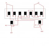
I might use the orig block to run a SOZ, using Caddock MP9100/100watt TO-247 resistors, we'll see:
Attachments
- Status
- This old topic is closed. If you want to reopen this topic, contact a moderator using the "Report Post" button.
- Home
- Amplifiers
- Pass Labs
- Water-cooled Aleph idea