I haven't tried it in analog circuits yet, but judging by how it behaves in digital circuits, I think it will be even better in analog circuits. I will soon be doing an op.amp test for IV stage with this type of regulator so I will be able to say more after that. That version will have an output voltage of +/-13V/200mA and an input voltage of around +/-20V. And I'm sorry, I don't have a pcb in Eagle to share at the moment. For now, these are still test versions of the PCB.Can You please share that small version of pcb in Eagle format and last version? What about preformance in analog sections or analog circuits?. Did You try it in that way?
Hello. I'll share the Eagle files as soon as I can. If I can even tonight.Can You please share that small version of pcb in Eagle format and last version? What about preformance in analog sections or analog circuits?. Did You try it in that way?
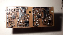
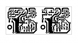
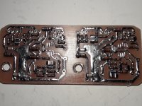
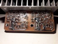
This is the new PCB for the +/-10V reg for my new test with the AD811 as the IV stage in my dac. I have to test it these days and maybe adjust the currents through CCSs. The references have already been tested and they are for 5V.
@Tix88, PCB is 85*38mm.
@Tix88, PCB is 85*38mm.
Attachments
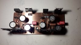
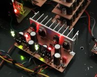
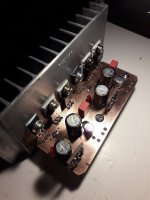
@viltsone , the last PCB has been working for more than a month in my DAC, I used an OPA1641 op amp and I must admit that the regulator works great, the shunt current is 135mA, which is quite enough to power two AD811s. In the following days, I plan to raise the voltage to +/-14V only by changing the reference voltage.
I will soon make a PCB for the 500mA version because I need it for eight pieces of PCM1702, the existing reg (also Walt Jung shunt) is on the edge with current.
I will soon make a PCB for the 500mA version because I need it for eight pieces of PCM1702, the existing reg (also Walt Jung shunt) is on the edge with current.
Attachments
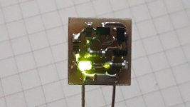
I don't have much free time these days so everything is a bit slow, the version for 500mA is not finished yet. Two low-noise 2.5V references were made just for this regulator.
I recently compared jfet op amps, ADA4610 is much better compared to OPA1641 and ADA4625-1 is the TOP op amp for this regulator, but it also has a TOP price")
The only drawback of the ADA4625-1 is that it requires much better decoupling than the ADA4610 or OPA1641. One of the advantages of ADA4625 is that it can work at 5V but then it needs a 1V reference like OPA1641 .
I recently compared jfet op amps, ADA4610 is much better compared to OPA1641 and ADA4625-1 is the TOP op amp for this regulator, but it also has a TOP price
The only drawback of the ADA4625-1 is that it requires much better decoupling than the ADA4610 or OPA1641. One of the advantages of ADA4625 is that it can work at 5V but then it needs a 1V reference like OPA1641 .
Attachments
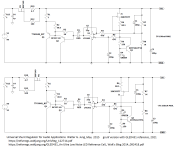
Hello everyone, the project is not dead on the contrary, it is in good health, but due to work the time to dedicate to the project is less and less. I update the schematics to version 7, I added the cascode as advised by Walt Jung himself, I think this will be the final version, because I spent too much time just designing the dac power supply, but still missing all the other areas to design, I am attaching the two diagrams for the Positive and Negative part, I only have a doubt about the connection of the cascode of the negative power supply, but I think some of you can correct me, I will limit myself to small updates of the pcb only.


Hi Grunfs, I was looking at the model of your ccs input with Biase multipler, I wanted to ask since I couldn't figure it out, but to implement it in negative feed, just flip the ccs and place it on the negative part? I hope you can clear this doubtI installed a new input CCS (BSP149, BSS159) yesterday,
Hi, I'm at the last design stage and I would like to try this css too, could you explain how to add it to my circuit? I see three terminals, and honestly I'm a bit confused
Just use + CCS and - CCS
forget the terminal labeled “ out”
I use a 500 ohm trimpot for currents up to 8 or 10 ma
I am using it in several power amps Krell, Ashly, Hafler. All with good results
You need at least 15 / 18 volts across this type of current source to work well. Not so good for preamps. Be careful not to overheat the jfets - use a series resistor to keep the voltage across the current source to 25 - 18 volts
Last edited:
@ticknpop
I get it, as I thought, so to use it in a negative Power supply, I assume you just have to reverse the sense of input right?
I think that using this type of CCS for the power supply of the DAC chip is a waste of energy, at this point it would be better to use the smooth Shunt with only one DN2540, what do you think? the power supplies need 16mA, is it worth using this type of power supply?
@Tix88 ,I hope this helps a lot , the true negative version(and positive) that I've been using for years, CCS are now with two mosfets and they should be turned the same way as in this scheme
Attachments
Last edited:
- Home
- Amplifiers
- Power Supplies
- Walt Jung shunt Design