Hi guys 
Just before starting the First One thread I have to get the info of delivery time for most important parts like output transistors, capacitors etc., to present you all an accurate information about waiting time to get the First One on the table.
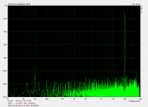
In the mean time here's 19+20 kHz intermodulation distortion measurement
1. 30 ppm THD19+20k 80 Vpp on 4 Ohm load
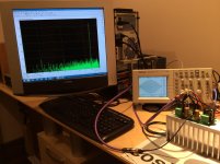
2. Setup
Just before starting the First One thread I have to get the info of delivery time for most important parts like output transistors, capacitors etc., to present you all an accurate information about waiting time to get the First One on the table.
In the mean time here's 19+20 kHz intermodulation distortion measurement
1. 30 ppm THD19+20k 80 Vpp on 4 Ohm load
2. Setup
Attachments
Both channels plays distorted?
VAS 12 mA bias OK (120 mV voltage drop between test points)?
Check if R19, R20 measures 10 Ohm
Check sinewaves scope plots with speakers (load) connected.
Check input cabling, GND.
Hi LC, one channel plays fine the other not.
I went through the setup process again for the faulty channel. VAS 12mA is fine, offset voltage is fine. Bias current can not be adjusted at all, its at 190mA.
R19 and R20 are bypassed as per your instructions. Grounding is good, heatsink is grounded too. All cabling is fine.
I need to go to a friends house to use an oscilloscope as mine died last night:-( I will report back and post pics of sinewaves under load.
BTW, I tested that is was not the speaker or source. It is definitely the one channel of VSSA.
Thanks
Hi Luke,
Definitely you should find out what is wrong with the BIAS setting and fix. If something is wrong there, not being able to set the bias might not the only side effect. I would check the voltage between collectors of the VAS transistors (or between the gates of the ALF, pins 2 and 4); how it reacts when you rotate the bias trimmer? If that is constant, then I would check the voltages around the TLVH431 chip. You should have a constant voltage between REF and Anode around 1,25V and a varying voltage between Anode and Cathode, depending on the trimmer position.
Cheers!
Hi Luke,
Definitely you should find out what is wrong with the BIAS setting and fix. If something is wrong there, not being able to set the bias might not the only side effect. I would check the voltage between collectors of the VAS transistors (or between the gates of the ALF, pins 2 and 4); how it reacts when you rotate the bias trimmer? If that is constant, then I would check the voltages around the TLVH431 chip. You should have a constant voltage between REF and Anode around 1,25V and a varying voltage between Anode and Cathode, depending on the trimmer position.
Cheers!
Thanks for your reply Metallicus. Heres what I get.
The voltages between bases varies from 1.6V to 1.9V from one end of pot to the other.
The Vref is 1.244V from anode to cathode of shunt.
The varying voltage from anode to cathode is 1.995V hard clockwise, and 1.612V ant clockwise.
Whats going on?
Hi Luke
If the bias voltage between the gates changes according to trimmer rotation than the output bias current should follow that too. Please check PCB and output mosfet transistor for some shorts. Also scope test is necessary to see the test signal or possibly some artefacts present. According to your measurement data all is OK. What about PSU?
Regards L.C.
Hi LC, I just reflowed the solder around the vas and output transistors and it now seems to work fine. Problem now is something has happened to the other channel. It hasn't been touched so Im a bit confused what's going on. I only noticed this as it was making a clicking noise on the speaker, fade in and stop then again. R21 and are open circuit and brown. BTW these are not in your schematic.
Can anything be done?
BTW I am using a 500VA torroid and PMI capacitance multiplier.
Thanks guys for all your help so far, I'll get there:-(
regards Luke
Can anything be done?
BTW I am using a 500VA torroid and PMI capacitance multiplier.
Thanks guys for all your help so far, I'll get there:-(
regards Luke
Last edited:
Hi Luke
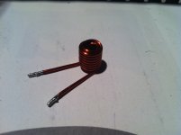
Replace burnt zobel resistors before proceeding. It looks you've got an oscillation on previously good channel. Since you don't have a scope to see what's the problem, I suggest you to use one of these (pic) on the output. It looks like yours speaker cables having highly capacitive character, causing problems. Or maybe you feed unintentionally some RF into input because of bad GND connection, etc.
Replace burnt zobel resistors before proceeding. It looks you've got an oscillation on previously good channel. Since you don't have a scope to see what's the problem, I suggest you to use one of these (pic) on the output. It looks like yours speaker cables having highly capacitive character, causing problems. Or maybe you feed unintentionally some RF into input because of bad GND connection, etc.
Attachments
LC, what can I do with the blown R21 and R22 resistors?
My speaker cable is capacitive. I made these and they need to be long.
DIY Cat5 Speaker Cables
OK, so any idea where to get these coils from? The first thing is to replace the resistors, this does not look an easy task, you think it can be done?
regards Luke
My speaker cable is capacitive. I made these and they need to be long.
DIY Cat5 Speaker Cables
OK, so any idea where to get these coils from? The first thing is to replace the resistors, this does not look an easy task, you think it can be done?
regards Luke
Of course it can be done hehe, just get them out and solder new ones, they're big enough so there should be no problem. ")
Output inductor from the pic has around 1 uH inductance and will prevent the VSSA to oscillate because of highly capacitive speaker cable you have. No worries since VSSA originally doesn't have inductor on the output, now the problem is solved.
Inductor from the pic can be made in no time from 1,5 mm Cu enameled wire, procedure how to make it is described in VSSA installation manual.
LC, what can I do with the blown R21 and R22 resistors?
Hi, the old pre BOM says "R21, R22 20ohm 0,75 W 1%, SMD 2010 (5025) 2 pcs".
If not a part you have, guess a 1-?w TH in vertical position would do
 .
.
Last edited:
L.C:You got your cables for extreme stability testings...My speaker cable is capacitive. I made these and they need to be long.
DIY Cat5 Speaker Cables
L.C:You got your cables for extreme stability testings...
I have checked it with inductive load and capacitors from 1 pF to 1 mF. First One with 0,25 uH on the output is unconditionally stable with or without signal present, even if driving with square waves up to 200 kHz.
Don't lie on this: When you use caps, the amp knows he is under surveillance ;-)I have checked it with inductive load and capacitors from 1 pF to 1 mF.
I have checked it with inductive load and capacitors from 1 pF to 1 mF. First One with 0,25 uH on the output is unconditionally stable with or without signal present, even if driving with square waves up to 200 kHz.
I parallel speaker with 100nF on my VSSA. It is stable. Yes!
LC, I cant remove these resistors (R21 and R22) being surface mount, so Im wondering if I can fix a 0.6 watt resistor. One end connects to ground, but I dont know where the other end connects to. I tried tracing with continuity test and the both seem to go no where?
Any help appreciated as always.
Any help appreciated as always.
R21, R22 can be easily removed from PCB with two soldering irons, one for each side of the resistor. Then solder the same type of SMD resistors 0,75 W.
One side goes to GND other to 47 nF to output, that is why only one shows continuity, other side is capacitive, so DC isolation.
Do you use output inductor from the pic now?
One side goes to GND other to 47 nF to output, that is why only one shows continuity, other side is capacitive, so DC isolation.
Do you use output inductor from the pic now?
Ah, I should have seen that
I can not get two soldering irons in this small gap so will add a normal 0.6W resistor to the bottom side of the board.
I will not connect it to my amp again until I have output inductors. I actually have some from an old amp lying around, I expect the value of this inductor is not so critical.
I can not get two soldering irons in this small gap so will add a normal 0.6W resistor to the bottom side of the board.
I will not connect it to my amp again until I have output inductors. I actually have some from an old amp lying around, I expect the value of this inductor is not so critical.
???I can not get two soldering irons in this small gap
You afraid me, with your new toy. No more comments about the sound...In the mean time here's 19+20 kHz intermodulation distortion measurement
Did-you moved to the dark side of the force ? The horrible army of objectivists marching and chanting numbers and figures? ;-)
Last edited:
No no no Esperado you know me very well. All this fuzz about the measurements was not for me, once I heard the VSSA I knew it is very good in all respects, that its parts/values were chosen optimally and that is clearly audible. The measurements are here to prove me that also raw technical specifications of the First One fits into frame of simm sceptics who's relying on specs only. Not only that, it proved also that is well over their simm results being in the top league.
One thing really learned during performing all these tests is ability of the amp to preserve input signal integrity, its harmonic structure with all artefacts present, in the output signal. And that is what can be easily seen in those plots and why the measurements are good and tells you more about correlation between measurements and expected sound quality.
One thing really learned during performing all these tests is ability of the amp to preserve input signal integrity, its harmonic structure with all artefacts present, in the output signal. And that is what can be easily seen in those plots and why the measurements are good and tells you more about correlation between measurements and expected sound quality.
Yes, i think i know-you a little.
But the pressure is so strong... I was fooled myself, when i was younger... Working too much in my lab with all the equipment (it is sooo simpler and reassuring). I remember to had fighted a lot, adding complexity, to design a amp with amazing measurements... Witch was... Just junk ! A sponge.
I'm afraid (and curious) some times, looking at some complex schematics in the CFA thread, build with simulators... All those diamonds, CSS, cascodes... I imagine the signal, lost in this labyrinth, asking for its way out like my eyes on the schematic
I know the time it takes to make each stage singing with joy, snappy... Working in sympathy with the previous and next one...
Yes, you know-it. Your VSSA is singing like a bird...
This said, and to stay a little technical ;-) i believe something has to be dig in both directions:
Diamond (or kind of) input to get rid of caps and low pass limitations. You reported the "nervous" character... well: balances between the two stages, isolation, (a resistance in serial between the two) ... i'm sure it can be pushed to perfection and i like the idea of isolation between input evils and loop...
Or Fets in input (i'm not good at this) with their immunity to HF? .
The second, obvious, is paralleled output devices to reduce OPS distortions.
- Home
- Vendor's Bazaar
- VSSA Lateral MosFet Amplifier