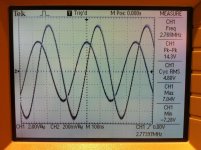
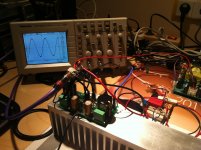
Today's measurement showing the First One's behaviour at 2,77 MHz sine signal.
We can see 0,9 Vpp input sine signal present on CH2 and 14,3 Vpp output signal on CH1
Calculations from the plot:
1. Voltage gain is x15,89 or +24 dB at 2,77 MHz
2. Linear voltage gain of the First One is +27 dB, meaning that 2,77 MHz is exactly -3 dB gain point
3. Phase shift at 2,77 MHz is 76°
4. 10 Ohm zobel load (Zr+Zc) dissipates 2,4 Wrms at 2,77 MHz
Attachments
Today's measurement showing the First One's behaviour at 2,77 MHz sine signal.
We can see 0,9 Vpp input sine signal present on CH2 and 14,3 Vpp output signal on CH1
Calculations from the plot:
1. Voltage gain is x15,89 or +24 dB at 2,77 MHz
2. Linear voltage gain of the First One is +27 dB, meaning that 2,77 MHz is exactly -3 dB gain point
3. Phase shift at 2,77 MHz is 76°
4. 10 Ohm zobel load (Zr+Zc) dissipates 2,4 Wrms at 2,77 MHz
Nice.... but I still waiting....
First One R&D finished
Over the weekend my task was to find proper output inductor and test the amp to all possible values of capacitance as a load, to be sure there are no chances for the amp to oscillate, no matter what kind of speaker cable is connected to its output terminals.
Lowest possible output serial inductance to fulfill upper demands is 0,2 uH, very practical small size still to be located on PCB.
Few pictures attached as follows:
1. Plot of 10 kHz/20 Vpp square waves on 6 Ohm +1 uF load. Upper trace amp's output in front of inductor, lower trace behind the 0,2 uH inductor.
2. 32 ppm THD10k spectrum 20 Vrms on 6 Ohm load (60 Wrms/6 Ohm)
3. 24 ppm THD10k spectrum 20 Vrms on 6 Ohm + 1 uF (90 Wrms/4,3 Ohm impedance). We can see that 1 uF loading capacitor completely filtered out third harmonic and elevated the second for 5 dB. The whole THD droped for 8 ppm but since third harmonic is also present in the input signal, this THD reduction is actually bad, not preserving the input signal integrity.
4. 0,2 uH output inductor and 1 uF loading capacitor in series with on/off switch
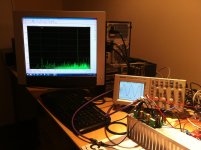
5. Complete measuring assembly
Attachments
-
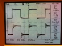 First One 10 kHz, 6 Ohm + 1 uF.jpg611.8 KB · Views: 1,000
 -
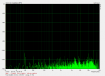 First One MIC 20 Vrms on 6 Ohm + no cap, 10 kHz.png86.7 KB · Views: 979
 -
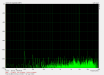 First One MIC 20 Vrms on 6 Ohm + 1uF cap, 10 kHz.png87 KB · Views: 935
 -
 First One 20 Vrms on 6 Ohm + 1 uF, 10 kHz.jpg512.3 KB · Views: 963
 -
 First One 20 Vrms on 6 Ohm , 10 kHz.jpg464.6 KB · Views: 260
Nice.... but I still waiting....
Yes very nice, I am glad that all necessary measurements needed are finished. Before producing this module in great quantities all parameters and loading conditions need to be tested, no delayed unexpected surprises possible.
According to all what I experienced with this module I can only say it is very robust, been over three exhibitions driven to its max and tortured with all kind of possible signals and provoked oscillations in my lab. First One amp module survived everything with the first pair of mosfets installed to a new PCB. Also the layout of this new PCB is just perfect which is clearly shown in amp's very predictable behaviour and low overall THD.
So now it is the time to open the First One thread, which I'll do tomorrow since today has been long day.
Regards to all, Lazy Cat

Last edited:
Congratulations
......and thanks LC.
Thanks, I had to test it extensively, no surprises for the builders, what you see is what you get.

Lazy Cat! VSSA - Great job!
Amplifier holds good external load.
It is known that due to the regeneration of the signal distortion on the acoustics of the load is increased tenfold, if not hundreds.
To avoid this, I would have made a negative output impedance as shown in the figure. It is sufficient to introduce an additional third wire to the acoustics in the open circuit NFB add a resistor R15. Rw - symbolized by the resistance of the speaker cable.
 [/URL][/IMG]
http://radikal.ru/fp/c9550226664d4ee497063d4d29fa8869] [/URL]
Best regards
Petr
Amplifier holds good external load.
It is known that due to the regeneration of the signal distortion on the acoustics of the load is increased tenfold, if not hundreds.
To avoid this, I would have made a negative output impedance as shown in the figure. It is sufficient to introduce an additional third wire to the acoustics in the open circuit NFB add a resistor R15. Rw - symbolized by the resistance of the speaker cable.

http://radikal.ru/fp/c9550226664d4ee497063d4d29fa8869]
 [/URL]
 Best regards
Petr
Yes, it works pretty good, and even better with a resitance added in the output. The negative point is it is not commun cabling, and industrial risk due to open loop if any cabling mistake.Rw - symbolized by the resistance of the speaker cable.
So, i will reserve such topology for active speakers while it is the situation where they are the least useful ;-).
Notice, in all situations, and regarding HF, shielded Speakers cables are always better.
acoustic cable
 [/URL][/IMG]
http://radikal.ru/fp/6b43340dd148496ba5ea4d84f382093b] [/URL]
best regards
Petr

http://radikal.ru/fp/6b43340dd148496ba5ea4d84f382093b]
 [/URL]
 best regards
Petr
Hi Lazy Cat, finally got two channels going from your group buy. One channel is perfect and the other sort of sets up, but the tr 3 does not set up the bias, no adjustment at all. Bias is fixed at 160mA and it plays music, only its not right, the mids are extremely distorted.
I didn't have a dummy load but, sinewave at 1, 10, and 20Khz looks fine and the same on both channels.
Any idea what might be wrong?
thanks
I didn't have a dummy load but, sinewave at 1, 10, and 20Khz looks fine and the same on both channels.
Any idea what might be wrong?
thanks
on my side I m also preparing for the integration of 4 VSSA and I just realized that the screws are connected to 0V...
I d prefer using non conductive screw in order to keep the enclosure disconect from 0V.
Is it ok ? or would this bring some side effect already known ?
Thank you
I d prefer using non conductive screw in order to keep the enclosure disconect from 0V.
Is it ok ? or would this bring some side effect already known ?
Thank you
Hi Lazy Cat, finally got two channels going from your group buy. One channel is perfect and the other sort of sets up, but the tr 3 does not set up the bias, no adjustment at all. Bias is fixed at 160mA and it plays music, only its not right, the mids are extremely distorted.
I didn't have a dummy load but, sinewave at 1, 10, and 20Khz looks fine and the same on both channels.
Any idea what might be wrong?
thanks
Both channels plays distorted?
VAS 12 mA bias OK (120 mV voltage drop between test points)?
Check if R19, R20 measures 10 Ohm
Check sinewaves scope plots with speakers (load) connected.
Check input cabling, GND.
on my side I m also preparing for the integration of 4 VSSA and I just realized that the screws are connected to 0V...
I d prefer using non conductive screw in order to keep the enclosure disconect from 0V.
Is it ok ? or would this bring some side effect already known ?
Thank you
Use plastic isolating washer (standard M3 size as transistor isolator) to isolate VAS screws from the heatsink. Plastic screws simply not providing enough tightening force.
Appendix: As I understand because of high speed amp it's important heatsink is grounded because of several reasons. Isolating screws is right method for making a CONTROLLED ground wiring scheme. But now remember before power on, that heatsink are bonded to starground in some way, either in the amps box or by temporary lead if running test setup on a table.
Sorry if I'm not right, then post is useless
ok guys, thx, basically you advise keeping heatsink to GND, through star-ground, if I use M3 washer. okay will do then.
Isolate two screws for isolation of groundloops to PCB (Only connection groundspade here), but at same make sure heatsink is grounded in some way. All this because heatsink without ground is antenna and a cap and it sits so close to VAS/OP devices not to mention PCB.
- Home
- Vendor's Bazaar
- VSSA Lateral MosFet Amplifier
