
What is this First One Amp module, any info? Is this your next project?
Yes new amp module named the First One, you could actually see it mounted on the heatsink on pic in post #3081.
")
How around 100Hz ?32 ppm THD10 at 100 Wrms/4 Ohm
Yes new amp module named the First One, you could actually see it mounted on the heatsink on pic in post #3081.
I like the circuit of VSSA can you post the circuit diagram of First One? A tentative one is fine with me.
Me wants First One badly!
Do
Me too.
LC you promise me to publish your amp at end of this year. But I must wait for few days....
How around 100Hz ?
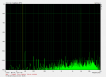
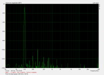
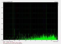
Here are the requested plots of the First One amplifier, 34 ppm THD 100Hz at 100 Wrms/4 Ohm
1. Input signal 100 Hz
2. Output signal 20 Vrms, no load
3. Output signal 20 Vrms on 4 Ohm
Attachments
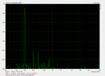
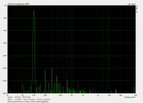
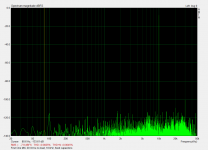
Now these 10 kHz plots and previous 100 Hz plots both series made today with fixed compensation SMD capacitors installed on PCB. Practically it is impossible to find the combination set by trimmer capacitors, but anyway very close results as before.
Plots of the First One amplifier, 40 ppm THD 10 kHz at 100 Wrms/4 Ohm
1. Input signal 10 kHz
2. Output signal 20 Vrms, no load
3. Output signal 20 Vrms on 4 Ohm
Plots of the First One amplifier, 40 ppm THD 10 kHz at 100 Wrms/4 Ohm
1. Input signal 10 kHz
2. Output signal 20 Vrms, no load
3. Output signal 20 Vrms on 4 Ohm
Attachments


Here are the requested plots of the First One amplifier, 34 ppm THD 100Hz at 100 Wrms/4 Ohm

Happy New Year...!
Happy New Year Andrej...Well in half an hour!
Thanks so much for your great work...In my opinion, you are a true creative genius and I have not said that on a DIY forum ever before!
Really excited about 2014, my speakers, your amps and a drop dead gorgeous media server and WiFi DAC to feed them with lots and lots of music!
Cheers
Derek.
Thanks guys for all encouraging words and happy New Year 2014. 
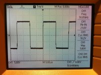
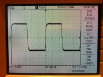
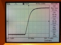
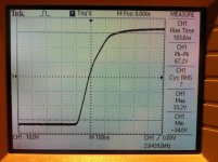
Few square waves and rise time measurements of the First One amplifier module.
1. 50 kHz
2. 200 kHz
3. mid signal level rise time
4. high signal level rise time
Calculation from pic.4, 60 V (90% Vpp) in 250 ns results in:
Slew Rate of 240 V/us
Few square waves and rise time measurements of the First One amplifier module.
1. 50 kHz
2. 200 kHz
3. mid signal level rise time
4. high signal level rise time
Calculation from pic.4, 60 V (90% Vpp) in 250 ns results in:
Slew Rate of 240 V/us
Attachments
Hi LC, happy new Year.Thanks guys for all encouraging words and happy New Year 2014.
Few square waves and rise time measurements of the First One amplifier module.
1. 50 kHz
2. 200 kHz
3. mid signal level rise time
4. high signal level rise time
Calculation from pic.4, 60 V (90% Vpp) in 250 ns results in:
Slew Rate of 240 V/us
Assuming a single pole bandwidth for the amp, there's a simple relation between bandwidth fc and the 10% to 90% risetime, tr.
fc = 0.35 / tr
You have 1.4 mhz...not bad
Amp more faster, more complex the operation measures if you want to see in depth. hehe!
- Home
- Vendor's Bazaar
- VSSA Lateral MosFet Amplifier