I can't figure out, are you up running again Luke.
Don't think lack of updates has coarsed the problems except good to have the amend info to the calibration procedure. Get amp running and calibrated with input shortened and no load at output as in manual + amend for calibration, remember 22ohm/5w on rails. After this amp should be able to be turned on with open input and no load at output without smoking those R21/22. If so now use amp for music, and if R21/22 goes smoking here (oscilation) either input or output courses this and turn off imediately. LC has tested amp to run with unshielded input cable, therefor think it's output where you need as described in maual RL parallel output filter (inductor/resistor). This needed because you use those fine made multi twisted speaker cables. But also the non potential ground at heatsinks could have made problems.
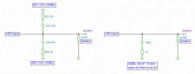
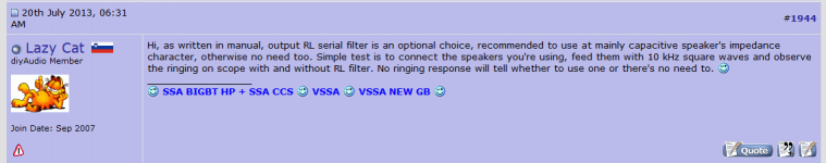
When you mention zobel i think you mean the inductor/resistor (RL output) at output to protect amp from capasive speaker/cable load. Zobel filter is build on PCB and consist of two caps and two resistors, these resitors is R21/22 (see first picture). If you can use those from parts bin inductors and 10 ohm resistors i don't no (see second picture for procedure).
..........Sadly I missed all the updates you have posted Byrtt, I hope this is not why I'm having these problems.
Perhaps it would have been better to start a build thread and capture all these and have updated doco on first post.
Don't think lack of updates has coarsed the problems except good to have the amend info to the calibration procedure. Get amp running and calibrated with input shortened and no load at output as in manual + amend for calibration, remember 22ohm/5w on rails. After this amp should be able to be turned on with open input and no load at output without smoking those R21/22. If so now use amp for music, and if R21/22 goes smoking here (oscilation) either input or output courses this and turn off imediately. LC has tested amp to run with unshielded input cable, therefor think it's output where you need as described in maual RL parallel output filter (inductor/resistor). This needed because you use those fine made multi twisted speaker cables. But also the non potential ground at heatsinks could have made problems.
Thanks Byrtt and LC, I will be more careful next time I power on. I thought it was fixed and after adding the zobel my problems would go away. I also have been thinking about sheilded cable for rca to module, I am using cat 5 for now as thats what I have on hand and its worked well for other projects.
While I'm at it, my zobels are not the ones recommended as I found them in my parts bin. They use a 10 ohm resistor and thicker gauge wire with a bigger diameter. I hope its ok to use these.
..........
When you mention zobel i think you mean the inductor/resistor (RL output) at output to protect amp from capasive speaker/cable load. Zobel filter is build on PCB and consist of two caps and two resistors, these resitors is R21/22 (see first picture). If you can use those from parts bin inductors and 10 ohm resistors i don't no (see second picture for procedure).
Attachments
Hi LC, you mean take all these semis out and test them?
No, with diode tester BJT-s can be tested in circuit.

Before proceeding to the next step you should always ask yourself a question how certain am I that all is OK. If the answer is not 100%, then recheck everything again to avoid failures.
Hi LC,
based on you findings around the First One, would you recomend a new configuration for the output of the VSSA 1.4 regarding Zobel and Inductance with or without resistor in paralell ?
No, no new recommendations whatsoever. In VSSA installation manual everything is explained, also parallel RL output filter and when to use it.

In First One amp L has just a little bit lower value according to measuring results and will be pre-installled on PCB.
New project point to point schematic VSSA.
 oh man, I can't stop laughing ... only need power for the light show and smoke
 Attachments

I can't figure out, are you up running again Luke.
Don't think lack of updates has coarsed the problems except good to have the amend info to the calibration procedure. Get amp running and calibrated with input shortened and no load at output as in manual + amend for calibration, remember 22ohm/5w on rails. After this amp should be able to be turned on with open input and no load at output without smoking those R21/22. If so now use amp for music, and if R21/22 goes smoking here (oscilation) either input or output courses this and turn off imediately. LC has tested amp to run with unshielded input cable, therefor think it's output where you need as described in maual RL parallel output filter (inductor/resistor). This needed because you use those fine made multi twisted speaker cables. But also the non potential ground at heatsinks could have made problems.
When you mention zobel i think you mean the inductor/resistor (RL output) at output to protect amp from capasive speaker/cable load. Zobel filter is build on PCB and consist of two caps and two resistors, these resitors is R21/22 (see first picture). If you can use those from parts bin inductors and 10 ohm resistors i don't no (see second picture for procedure).
hi Byrtt, Im not running. I dont know if I'll ever get this going. Im not sure if I have valid readings, I took out a VAS transistor cos the readings didnt look good, when I compared it to the good one it was identical. I suspect the mosfet may be suspect, but dont really know and I don't have one. Apart from that this is unlike anything I have seen and getting too hard.
I may leave it for a couple of days as I'm loosing interest for now. Thanks for your help
Thanks for feedback Luke, thought you were up running and sad to hear you are not.
If LC pops up follow his suggests course he's very pro (I am hobbyist).
Else I suggest following because I understand you have one good running module. Use your DMM (resistens mode and diode mode) and make compare measurement results between good and bad module at different location point between modules, clue is that when those measurements show bigger difference in readings, components in that area should be investigated further for malfunction.
Before making those measurements maybe good idea to get the three multiturn pots at same resistence readings as on the good module.
Last edited:
yes one of my readings is off, but its not obvious, just alot different, not dead short or dead open. I got there reading across the vas so cut its pins, only real way to get it our due to the compact and smd nature of this module. When compared it to a good one its the same. I suspect its the fet that caused this reading error. I will post the difference when I get back to it. At theeEnd of the day, there isn't many parts
I hope if its the output I can buy one from a member here. It will be hard to source here.
I hope if its the output I can buy one from a member here. It will be hard to source here.
Hi Luke try to even the resistence readings for the three legs on all three multiturn pots, so as the bad reads same as the good one, and see if this helps. If you end up needing ALF output device and can't source it i can send you one. I can get a new one from RS-online at cost 16,50€. So cost for you 16,50€ + postal Denmark-Australia. Good soldering.
..........postal Denmark-Australia..........
Took closer look should be postal Denmark-New Zealand, sorry.
I have the part so PM me if necessary.
Hi,
Apologies for not reading through more than 3000 posts in this thread but has anyone made physical THD+IMD+N measurements from a VSSA? I'm very interested in building a few if the quality stacks up to more traditional designs like Blameless and Honey Badger, or is at least a significant improvement on LM3886.
Apologies for not reading through more than 3000 posts in this thread
but has anyone made physical THD+IMD+N measurements from a VSSA? I'm very interested in building a few if the quality stacks up to more traditional designs like Blameless and Honey Badger, or is at least a significant improvement on LM3886.Hi,
Apologies for not reading through more than 3000 posts in this thread
See at your link member jkuetemann made good links if you want to go VSSA way. This threads VSSA was set up at higher bandwidth, but as we are in commercial sector final schematic is not available, and group buy is closed. If very fine specs is of interest LC's new VSSA called "First One" is at production step here http://www.diyaudio.com/forums/vendors-bazaar/248996-first-one-mosfet-amplifier-module.html, but is at higher power output than you request.
First One looks nice but too $$$ for me. I'm not looking for prebuilt either.
Try to DIY the VSSA first. If you believe it is an improvement over the blameless then I believe First One is not expensive at all.
More than that, I was, on my side, very surprised by the *low* price of those modules, if you consider how it should cost to order the parts on Internet, plus the saved time to list them, build them and tune the amps...I believe First One is not expensive at all.
And, if we consider both the incredible quality/price ratio and the time spend by L.C. to design those fine amps, it is, really, just a gift.
First One looks nice but too $$$ for me. I'm not looking for prebuilt either.
laplace, check with touchdown - he had a kit for sale earlier today. Search for him under swap meet. Very good price I think.
Regards
- Home
- Vendor's Bazaar
- VSSA Lateral MosFet Amplifier