In a way, yes, in an other, you still can use 4Ohms, if you ensure that, with some external protection, limiting the input level, as an example, you will never ask too much peak current from the power devices.
Cool! Worth a try for sure since I have 4 modules..

Nice work!
Do
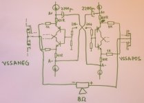
.....Could you do a little schematic of the cap connection between the two modules?.....
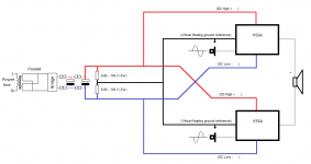
Hi Do, metallicus69 reference to post #1660. I attach here picture from that post where he makes virtuel ground in X for C2/3/4/5 between two modules. Also see my simplified schematic with more vituel ground for PSU, and last Christope's post #2432 explanation. Only drawback seems you need balanced pre signal and if not having one need to build a splitter with specs as good or better than your single ended pre.
Attachments
Last edited:
Hi Pete.....I guess I am going to have to toast both you, and LC this weekend....
 .....
..... .....
..... .....
.....  .....
.....  .....
..... ..........see you monday, good weekend.
Last edited:
Hi Pete
Thanks for the diagrams! Just wanted to let you know that this works
I used two VSSA modules. First calibrated them independently according to the instructions delivered. Then removed the C2 and C3 caps and mounted the ELCaps Nichicon KT (6800uF) according to the schematic in #1660.
No oscillations, no hum, no unwanted noise. Just wanted good nice sound
...
As I have a reason to celebrate, no more work over the weekend...
Cheers!
Bravo Radu, very nice experimental work.
VSSA in full balanced version hehe, perfectly, even more if the rest of the system is balanced.
I very much like your findings that parallel film cap across elco is an improvement, for the same reason I provided both 10 uF in VSSA. I also found out that this cap should have non resonant high-Q dielectric material, like film caps are.
Just please have in mind output current limitation, but as I see what are you're doing I am sure we can trust you by that.
Enjoy your work.
I guess I am going to have to toast both you, and LC this weekend. By an interesting coincidence, a couple bottles with a very appropriate label were given to me a few days ago just as I was reading about LC's latest project...
hehe we all could find a moment in time this weekend and toast to each other. This VSSA project brought so much joy to many people, so much positive energy, so many new friendships arised that I am simply amazed.
All the best to everyone gathered on this project.

hehe we all could find a moment in time this weekend and toast to each other. This VSSA project brought so much joy to many people, so much positive energy, so many new friendships arised that I am simply amazed.
All the best to everyone gathered on this project.
Nice words Andrej thank you, it is a pleasure to follow. VSSA project brought 6 times very interesting threads regarding VSSA/PSU, and new baby "First One" will follow.
PS!!! Just took second closer look at metallicus69 post #2816 pictures, he tweaked the two onboard PSU cap banks from 2x1mF to 2x2,2mF. There's also link in his post to see nice ballanced preamp that will be feeding VSSA's.
Last edited:
Hi mates,
Thanks for the nice words! I perceived the V/T/BIGBT/SSA as a great finding from the beginning; you know, like a girl you fall in love with at the first sight... but let's keep the discussion technical
As soon as I received the previous batch of 4 boards I started to arrange them and I noticed the perspective of testing this arrangement. If you put two boards aside with the inputs in close proximity, as you can see from my pictures, everything comes in naturally, without too many artifacts in the build. Taking into account that every amp has an input resistive load, you don't even need to get the balanced GND input wire to the boards, as the arrangement creates an input virtual GND.
Honestly, I think the best win for the balanced VSSA is for 8 OHM loads. If Andrej tested that one channel works for 4 OHM up to +/- 45V, then the balanced one will work as well into 8 OHMS, in the same conditions. Well, I can see that only one MOS can handle 8A of current, so probably the best top working voltage would be around +/-37-38V, but if you use this amp in home conditions, and your supply rails may fail under load a few volts, we must be probably safe even with higher voltages, especially with lower power transformer.
If you intend to go on 4 OHMS, or even lower, you should consider how one amp can cope with your load divided by two. So for 4 OHM, the load is actually 2 OHMS for one VSSA; that means Vmax to be +/-21-22V, considering Imax=8A and 5V drop over MOSFETs. So if you only want to hunt higher power, it does not make much sense; however, balanced at much lower voltage, might still raise your interest, as the price for capacitors is much better in 25V range; it's up to you what you might like. if load is lower than 4 ohms, I don't think you can get anywhere with balanced VSSA using Andrej's boards; they are specified for a minimum of +/-20V. I am sorry if I ruined some dreams, but let's be realistic. 8 Amps are 8 AMPS. Please think well if this arrangement is worthy or not for your case, before investing in additional hardware or pushing existing one above the limits!
In my case this arrangement is perfect; I use 8 OHM wide range speakers, without separation filters, meaning not too many non-linearities in the impedance; using an equalizer that takes extremities 17-18dB higher than the middle range, I need better reserve of power, but not continuously.
Sure, if you use double die transistors, or you parallel them, that's a different discussion!!! I wanted to let you know the reality with Group Buy boards, before letting you destroying them.
@LC: especially thank you for the high quality PCBs and components. Resistors in the feedback loop came up with a tolerance of less that 0.1%. this matters most in this experiment; transistors hFE were also extremely close according to ATLAS reading (@ 5 mA); and mechanical stability is astonishing as well.
Cheers everyone!
Hmmm, I must have missed that, my datasheet does not mention 4-Ohms at all....If Andrej tested that one channel works for 4 OHM up to +/- 45V...
That would be over 200W into a 4-ohm load, from one TO-264...
For a single board will a 330kva transformer be large enough to handle full load output? I have a number of Signal brand BL-1733A transformers with multiple output taps. I am thinking of using the 28 volt ac output before the rectifier operating PMI/Evil cap multiplier and then the VSSA. Anyone see a problem with this?
Thank you,
Steven
Thank you,
Steven
Excellent bridged VSSA amp!
I guess I can forget LM3886 for that purpose now...
Anyway, as I got frustrated after failure to correctly bias the VSSA-DIY (I suspect my 2SJ162) and while I wait for new MOSFET to arrive, I decided to adapt the VSSA to a BJT output, with the simple cap. multiplier used for the SSA-BJT and 39pF caps between b and c of the VAS transistors, just in case. Miraculously, it worked at first attempt and with reasonable numbers and excellent sound.
DC offset was 27mV, cold (without 1M trimmers) and raised to 65mV when playing; current for the VAS was 13mA on cold and raised to 16,5mV when hot; total bias was around 160mA cold...now I have to make a star ground and add some Russian film caps to the rails.
Thanks again to the generous and not so lazy LazyCat.
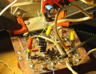
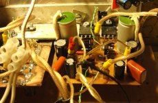
There goes a picture of the VSSA DIY (in positive) and then a second one of the board adapted to BJT.
I guess I can forget LM3886 for that purpose now...
Anyway, as I got frustrated after failure to correctly bias the VSSA-DIY (I suspect my 2SJ162) and while I wait for new MOSFET to arrive, I decided to adapt the VSSA to a BJT output, with the simple cap. multiplier used for the SSA-BJT and 39pF caps between b and c of the VAS transistors, just in case. Miraculously, it worked at first attempt and with reasonable numbers and excellent sound.
DC offset was 27mV, cold (without 1M trimmers) and raised to 65mV when playing; current for the VAS was 13mA on cold and raised to 16,5mV when hot; total bias was around 160mA cold...now I have to make a star ground and add some Russian film caps to the rails.
Thanks again to the generous and not so lazy LazyCat.
There goes a picture of the VSSA DIY (in positive) and then a second one of the board adapted to BJT.
Attachments
No problem at all, more than large enough for one channel. 28V AC nominal, will give you 75 watts (conservative estimate) before clipping. So in your case the nominal transformer power will be over 4x maximum output power into 8 ohms. I have been using either 300VA (not at full power) or 400VA during testing, for both channels, with no problems.For a single board will a 330kva transformer be large enough to handle full load output?...
Excellent bridged VSSA amp!
I guess I can forget LM3886 for that purpose now...
Anyway, as I got frustrated after failure to correctly bias the VSSA-DIY (I suspect my 2SJ162) and while I wait for new MOSFET to arrive, I decided to adapt the VSSA to a BJT output, with the simple cap. multiplier used for the SSA-BJT and 39pF caps between b and c of the VAS transistors, just in case. Miraculously, it worked at first attempt and with reasonable numbers and excellent sound.
DC offset was 27mV, cold (without 1M trimmers) and raised to 65mV when playing; current for the VAS was 13mA on cold and raised to 16,5mV when hot; total bias was around 160mA cold...now I have to make a star ground and add some Russian film caps to the rails.
Thanks again to the generous and not so lazy LazyCat.
There goes a picture of the VSSA DIY (in positive) and then a second one of the board adapted to BJT.
MASTER MAXLORENZ, not only words, FACTS.
MASTER MAXLORENZ, not only words, FACTS.
You're too kind...I am only an amateur trying to figure out how the H*** do amps work. I guess I still have begginers luck from time to time.
Oh! I didn't add Zobel network but I could add it underneath if something strange happens...the neighbors you know...
Best regards,
M.
PMI,
Thanks for the answer. There is also a 48 volt tap but I figured that voltage would be much to high for the devices on the boards. I can use one of the other lower voltage taps for a lower power output for a dome tweeter after an active X-over section. The taps are 14, 24, 28, and 48 volts. I have about 10 of those transformers so one per channel seems like the way to go for the margin that it will allow. Figure that should be enough power for 1-6 1/2" cone driver with about an 86db efficiency. These drivers have a voice-coil that can handle a max of 150 watts but I have never had to push them to anywhere that level before they would drive you out of the room! Thank you for the cap multipliers and LC for the boards.
Steven
Last edited:
With so many taps, you have to pay some attention to the intended power output of each one. One cannot necessarily assume that anything like the full rated power will be available from any one or any combination. The core will be a size that can support the maximum rated VA, but some of the taps may be intended for very low current output. In general, the thick wires will correspond to the higher power taps... I would post a question in the power supply forum....The taps are 14, 24, 28, and 48 volts...
With that particular transformer, 48V may be the main output. It may also be 48V center tapped, which would give you +/-24V AC, or about +/-34~5V DC after the Cap multiplier.
If so, this would give you about 3.25A per rail for one channel. I would fuse the CM board at 2A for testing, and no more than 3A (fast-blow) when you get it together to lower the risk of nasty surprises.
On the label, it may be something like: 0-24-48, and 0-14-28, separate, and center tapped windings. It is just a guess, but that is what would make sense for audio, and would also be ideal for your use... you just have to figure out which is the main power secondary.
PMI, You are correct in that the label is just as you guessed. "On the label, it may be something like: 0-24-48, and 0-14-28" Now I have to figure out what is what. I'll see if I can find the spec sheet on their site for this transformer, I think it is still a production part.
The other thing I can see is that yes there are two different sized wire gauges going on. The connectors are even different sizes for the two different sets of connections.
The other thing I can see is that yes there are two different sized wire gauges going on. The connectors are even different sizes for the two different sets of connections.
Last edited:
- Home
- Vendor's Bazaar
- VSSA Lateral MosFet Amplifier