If the 10R burns, is definitely not the fault of the psuI remember that there was a problem with one resistor of the VSSA when powered with the SMPS...I asume that this won't be the case with "the One".
Best wishes with the new project.
M.
")
I believe it was posted that the manufacturer substituted a resistor which did not have a very high surge rating.If the 10R burns, is definitely not the fault of the psu
This resistor is in series with the rail voltage, and carries the current from the supply terminal to a 1000uFd cap. When power is first applied to the board, the cap charges up to the rail voltage through a diode, and this resistor. In other words, there is an inrush.
This is typically a non-issue with a linear power supply, especially if there is any kind of soft start.
I believe it was also posted that the output voltage of the Hypex supply goes from zero to nominal in a very short time. Almost instant turnon. The caps see the full 45V instantly. The momentary inrush is very large... 45V/10R at start.
Under those conditions, the inrush destroyed the resistor.
Since then, it has been recommended to eliminate the resistor completely, so for people who implemented this mod, the issue no longer exists, even with the hypex supply.
What ?? SMPS without soft start ?I believe it was also posted that the output voltage of the Hypex supply goes from zero to nominal in a very short time. Almost instant turnon.
Affraying, even for their caps.
I believe it was posted that the manufacturer substituted a resistor which did not have a very high surge rating.
This resistor is in series with the rail voltage, and carries the current from the supply terminal to a 1000uFd cap. When power is first applied to the board, the cap charges up to the rail voltage through a diode, and this resistor. In other words, there is an inrush.
This is typically a non-issue with a linear power supply, especially if there is any kind of soft start.
I believe it was also posted that the output voltage of the Hypex supply goes from zero to nominal in a very short time. Almost instant turnon. The caps see the full 45V instantly. The momentary inrush is very large... 45V/10R at start.
Under those conditions, the inrush destroyed the resistor.
Since then, it has been recommended to eliminate the resistor completely, so for people who implemented this mod, the issue no longer exists, even with the hypex supply.
LC wrote: Tnx PMI, exactly as you have described regards 10 Ohm inrush surge. As recommended RD in both rails should be shorted for sound improvement. No issue after that.
OK. Thank you guys. I did the mod for sound improvement. So, the answer is that First One will have no issues with SMPS.
Dear Dady,
Be patient. There are no more VSSA kits, but LC will offer a still better amp "soon":
VSSA PCB GB is finished, nothing left here, no ALFs, not even one test PCB
As soon as the First One modules will be ready, new thread will be started and new GB announced.
Yet, the VSSA is simple enough to make our own PCBs or profit from other mate's effort like PMI's or Shaan's.
That said, my first attempts failed and I suspect my J162 are fake...
Waiting for the new to arrive and considering the double ALF FET that LC uses.
Cheers,
M.
Just for reference, I have been buying the SK1058 and SJ162 from Tayda Electronics online, they ship very quickly for being overseas. I believe they were recommended in some other thread.... I suspect my J162 are fake...
Waiting for the new to arrive and considering the double ALF FET that LC uses.
One reason why I have the Capacitance Multiplier PSU. The soft start for the amp boards is inherent in the design, and even with a couple amps which are not symmetrical like Lazy Cat's, the turnon "thump" (or click) is reduced to in-audible.What ?? SMPS without soft start ?
Affraying, even for their caps.
However, as Lazy Cat has pointed out, the elephant in the room (or chassis) that those of us who like linear supplies usually fail to mention but cannot hide, is the transformer...
With my huge 1000Va one and big caps, and without a soft start, all my village could know when i power-on my ampHowever, as Lazy Cat has pointed out, the elephant in the room (or chassis) that those of us who like linear supplies usually fail to mention but cannot hide, is the transformer...
Oye Lazy Cat! Your personal mail box is full, I trying of say something about get two VSSA with SMPS
Could you answer please?
Best Regards
Hi dady

No VSSA PCB set anymore.

There will be the First One amplifier module released soon, be patient please.

What ?? SMPS without soft start ?
Affraying, even for their caps.
All Hypex SMPS-s have soft start and inrush current control, no doubt about that.
The thing is that after powering up soft start and check up cycle takes first two seconds. In between this cycle output voltage is zero. After these two seconds output voltage goes to nominal rail value in a micro second, on the scope screen it looks like perfect square ramp - from zero to max., meaning this ramp has slew rate of 100 V/us. 10 Ohm resistor faced 45 V/10 Ohm peak current, so only the transient current type resistor could survive this peak, the one producer installed was normal SMD resistor, blown when faced this peak.
Hopefully this is cleared.
SMPS1200A400 has completely the same starting up sequence and output voltage square.
The First One amp will be ready for the rail's starting ramp.

Hi dady
No VSSA PCB set anymore.
There will be the First One amplifier module released soon, be patient please.
Thanks a lot, dovro.
You are welcome.
Yami:
ALF08NP16V5 Semelab | MOSFET Audio N/P-Ch 160V 8A TO-247-5 | 737-9615 | Welcome to RS Online
Yami:
ALF08NP16V5 Semelab | MOSFET Audio N/P-Ch 160V 8A TO-247-5 | 737-9615 | Welcome to RS Online
IT WORKS! IT WORKS! IT WORKS!
Just wanted to let you know that this works
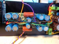
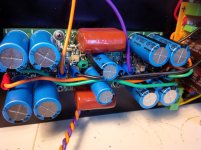
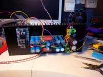
I used two VSSA modules. First calibrated them independently according to the instructions delivered. Then removed the C2 and C3 caps and mounted the ELCaps Nichicon KT (6800uF) according to the schematic in #1660.
No oscillations, no hum, no unwanted noise. Just wanted good nice sound Especially after bypassing the elcos with the film caps the sound was even more clear (almost night and day difference).
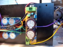
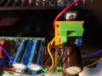
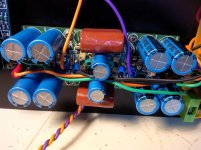
For the moment only on test bench. the serious tests will happen on next week (have to finish the other channel as well), but I can share some pictures. In the test I used my raw power supply (variac + trafo+bridge+2x5500uF) so there are no reasons to compare yet with simple VSSA, that has a huge and serious supply. As you may have spotted, I use the Cap multiplier ( a "hardcore" version, with a mix of through hole and SMD components). Voltage drop ~500mV and it stays fine. All calibrated for a +/-45V voltage. The heatsink is quite serious for one channel (12x30cm with 4cm height) and hopefully will chill out the beast well enough. I have the option to use coolers as well on high temperature, and 12cm ones can be quite silent, especially if triggered with a temp sensor. I hope I can do it without them, anyway.
i have a coldamp SMPS (800W continuous/1300W peak) but that means common ground for L and R. This one is great, I used one in the past for another power amp.
500VA trafo I have might be on the low side, and offers only +/- 35V after Cap multiplier. I guess I will go for SMPS.
As I have a reason to celebrate, no more work over the weekend...
Cheers!
Hi Andrej and diyAudio fellows.
I am now thinking of a balanced (X)VSSA, that could use the simplicity of this design and the output of JC-80. Of course, this is just a rough idea, and I tried to cover it in the attached picture.
Basically, I think that instead of running the ElCaps to the ground in the feedback nodes, we can maybe "X" them between two VSSA modules, so they will become a true balanced unit.
I am interested to learn if this looks valid and realistic. I thought I will better share this idea, because LC or somebody else can validate/improve it either by building or by simulation before it will reach my soldering iron - or other way of saying, rusting for years in my brain
Cheers!
P.S.: I will build the VSSA anyway in the next month, as I am sure it will be a major step forward, but I need to have a future next project
Just wanted to let you know that this works
I used two VSSA modules. First calibrated them independently according to the instructions delivered. Then removed the C2 and C3 caps and mounted the ELCaps Nichicon KT (6800uF) according to the schematic in #1660.
No oscillations, no hum, no unwanted noise. Just wanted good nice sound
Especially after bypassing the elcos with the film caps the sound was even more clear (almost night and day difference).For the moment only on test bench. the serious tests will happen on next week (have to finish the other channel as well), but I can share some pictures. In the test I used my raw power supply (variac + trafo+bridge+2x5500uF) so there are no reasons to compare yet with simple VSSA, that has a huge and serious supply. As you may have spotted, I use the Cap multiplier ( a "hardcore" version, with a mix of through hole and SMD components). Voltage drop ~500mV and it stays fine. All calibrated for a +/-45V voltage. The heatsink is quite serious for one channel (12x30cm with 4cm height) and hopefully will chill out the beast well enough. I have the option to use coolers as well on high temperature, and 12cm ones can be quite silent, especially if triggered with a temp sensor. I hope I can do it without them, anyway.
i have a coldamp SMPS (800W continuous/1300W peak) but that means common ground for L and R. This one is great, I used one in the past for another power amp.
500VA trafo I have might be on the low side, and offers only +/- 35V after Cap multiplier. I guess I will go for SMPS.
As I have a reason to celebrate, no more work over the weekend...
Cheers!
Attachments
Impressing and congratulation, handmade and well thought tweaks.....As I have a reason to celebrate, no more work over the weekend...
Cheers!
Serial audio signal all through amp and high power will love to hear about listening tests.
Thanks for teaser, best regards and weekend
Last edited:
Just wanted to let you know that this works
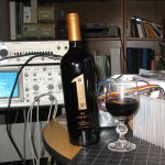
 This is VERY cool! Congratulations.
 I guess I am going to have to toast both you, and LC this weekend. By an interesting coincidence, a couple bottles with a very appropriate label were given to me a few days ago just as I was reading about LC's latest project...
Attachments
Just wanted to let you know that this works
I used two VSSA modules. First calibrated them independently according to the instructions delivered. Then removed the C2 and C3 caps and mounted the ELCaps Nichicon KT (6800uF) according to the schematic in #1660.
No oscillations, no hum, no unwanted noise. Just wanted good nice sound
For the moment only on test bench. the serious tests will happen on next week (have to finish the other channel as well), but I can share some pictures. In the test I used my raw power supply (variac + trafo+bridge+2x5500uF) so there are no reasons to compare yet with simple VSSA, that has a huge and serious supply. As you may have spotted, I use the Cap multiplier ( a "hardcore" version, with a mix of through hole and SMD components). Voltage drop ~500mV and it stays fine. All calibrated for a +/-45V voltage. The heatsink is quite serious for one channel (12x30cm with 4cm height) and hopefully will chill out the beast well enough. I have the option to use coolers as well on high temperature, and 12cm ones can be quite silent, especially if triggered with a temp sensor. I hope I can do it without them, anyway.
i have a coldamp SMPS (800W continuous/1300W peak) but that means common ground for L and R. This one is great, I used one in the past for another power amp.
500VA trafo I have might be on the low side, and offers only +/- 35V after Cap multiplier. I guess I will go for SMPS.
As I have a reason to celebrate, no more work over the weekend...
Cheers!
So this is in fact bridging the amps, right? In this configuration, I assume there's no more support for 4 Ohms load, only 8 Ohms and 16 Ohms load?
Could you do a little schematic of the cap connection between the two modules?
Thanks
Do
In a way, yes, in an other, you still can use 4Ohms, if you ensure that, with some external protection, limiting the input level, as an example, you will never ask too much peak current from the power devices.So this is in fact bridging the amps, right? In this configuration, I assume there's no more support for 4 Ohms load, only 8 Ohms and 16 Ohms load?
- Home
- Vendor's Bazaar
- VSSA Lateral MosFet Amplifier