It may take a bit more time, but two independent center tapped windings are better than if it had been closer to your original post. It seems like a good find."On the label, it may be something like: 0-24-48, and 0-14-28" Now I have to figure out what is what...
Both I and a couple other people are doing our best to keep a Through-Hole version alive for a while, for those who don't mind soldering their own components......now that VSSA is out of production...
"All hail, Lazy Cat! Hail to thee that shalt be amplifier King hereafter!"
 Besides, if VSSA is any indication, Lazy Cat's new project will be an even bigger bang for your buck, and does not seem to be far behind...
 500VA trafo I have might be on the low side, and offers only +/- 35V after Cap multiplier.
exactly what you need for balanced drive
low impedance speaker load will hurt less
Both I and a couple other people are doing our best to keep a Through-Hole version alive for a while, for those who don't mind soldering their own components...
I know, dear PMI, but this VSSA, as the name implies, is very simple to make an one can practice with the "quick and dirty" method of one's preference, if one is impatient enough not to wait for the PCB's to be made and shipped, etc...
It is a good way to practice and develop our own layout concepts...
as I usualy have scruples about other people's decisions...Good luck with your effort.
M.
¡Habemus stereum!
All I can say is that if you run out of lateral FETs, you can give BJT a try without shame.
"All hail, Lazy Cat! Hail to thee that shalt be amplifier King hereafter!"
Very nice DIY work Mauricio, congratulation!

This topology is soo parts forgiving that it would work also with Germanium BJT-s or tube output stage with transformer.

And at the end is always nice the to hear clear sounds out of speaker.
Too true, and the satisfaction in etching or wiring one up quickly, can't be beat, although compared to Shaan (my inspiration) and a couple other people, I took my time to get there...I know, dear PMI, but this VSSA, as the name implies, is very simple to make an one can practice with the "quick and dirty" method of one's preference, if one is impatient enough not to wait for the PCB's to be made and shipped, etc...
It is a good way to practice and develop our own layout concepts...
Good luck with your effort.
M.

I think there are at least six single layer etch-able versions with pdf files posted in Shaan's PeeCeeBee thread
Besides, if VSSA is any indication, Lazy Cat's new project will be an even bigger bang for your buck, and does not seem to be far behind...
Just finalizing the layout out of First One's prototypes PCB. Some minor changes, different parts, but in majority almost the same as first three First One amps already made.
All parts will be preinstalled on PCB, for some orders also ready-calibrated modules will be available.
Hopefully this week I'll make and test zero series modules before green light is on for a big one - series of thousand or more.
Regards Lazy Cat, meeow
You should change your forum name to "Busy Cat"!
Just to put my name in the Q for a stereo pair of boards, complete and, if possible, calibrated! [I have various uncalibrated DDMs, but have recently had problems; being old Philips and Keightly, recalibration would cost 300% of their value!!]
Just to put my name in the Q for a stereo pair of boards, complete and, if possible, calibrated! [I have various uncalibrated DDMs, but have recently had problems; being old Philips and Keightly, recalibration would cost 300% of their value!!
]PMI,
Thanks again for the information and confirmation. So I have a bunch of these then that appear to have two separate sets of windings on a common core. I don't want to rip into one of these but perhaps they are what you guys call bifilar wound. I think I paid about $10.00 per transformer when I got then back quit some time ago from Apex Jr. supply.
Thanks again for the information and confirmation. So I have a bunch of these then that appear to have two separate sets of windings on a common core. I don't want to rip into one of these but perhaps they are what you guys call bifilar wound. I think I paid about $10.00 per transformer when I got then back quit some time ago from Apex Jr. supply.
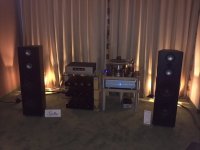
This weekend First One amp played in a Gallus audio room at Hi-Files show in Belgrade.
As I read some comments, visitors were quite positive about the sound of the system.
As I read some comments, visitors were quite positive about the sound of the system.
Attachments
Very nice DIY work Mauricio, congratulation!
This topology is soo parts forgiving that it would work also with Germanium BJT-s or tube output stage with transformer.
And at the end is always nice the to hear clear sounds out of speaker.
Thank you dear Andrej.
When the P-channel arrive I will perhaps know if the former were bad or if I failed to bias them correctly...
I believe we can't thank you enough for your generosity in sharing your savoir faire. I mean, in the case of being able to develop the topology to its last consequences, the majority of us, me included
, would have kept the secret and make profit of it, because we are living in a world that promotes iniciative but that also promotes selfishness so efforts like yours, consisting of, at least, designing, testing, re-designing, re-testing, searching the parts from the BOM, making the boards, populating them, and at last, shipping them, and all for a mere nominal price, these efforts, I was saying, are to be applauded. We are all expectant about the new project and wish you best of lucks.
Sincerely yours,
Mauricio.
I have a tip for the VSSA boards from LC: To allow a much easier adjustment of the trimmers TR1 and TR2 I have soldered 470 OHMs resistors on top of each R9 and R10.
This might be helpful if some trimmers are a bit "jumpy" around the necessary position.
you can try also 430 OHMs, but you may get out of the useful range, so 470 is more conservative.
Cheers!
This might be helpful if some trimmers are a bit "jumpy" around the necessary position.
you can try also 430 OHMs, but you may get out of the useful range, so 470 is more conservative.
Cheers!
exactly what you need for balanced drive
low impedance speaker load will hurt less
Yes, you are right in this respect. Unfortunately, I cannot power both channels with one trafo; 500VA for 4 modules may be on the lower limit according to my taste, and probably the voltage will fell too much in peaks.
The trafo is built with 4 coils of 28Vac to power 4 diode bridges each, originally intended for a dual mono LM3886 amplifier. I used another one to power my first set of VSSA stereo amplifier, and I don't like to dismantle that one...
On the other hand, the SMPS can be adjusted down to +/-38V as well; will it possibly lose power ( I see a maximum 7A output current in the datasheet)? The size fits better and the whole amp it's quite lightweight but I don't like that max 7A in the specs.
Tough decisions
The current output maximum should not go down. Maximum power should simply drop in proportion to the selected output voltage. I would email the company and make sure.On the other hand, the SMPS can be adjusted down to +/-38V as well; will it possibly lose power ( I see a maximum 7A output current in the datasheet)? ...
So, if I am reading this correctly, at +/- 38V and 7A, you would get 266W nominal, say 240~250 actual. It should be the equivalent of what you can get from a 500VA transformer with 28V secondary, or a few percent more.
It will get VERY hot at that point (note the provision for fan cooling). Fortunately small and quiet computer fans are perfect for that job, and inexpensive.
It may not provide the kind of peak over-current you may be used to from a conventional power supply. Note the two pair 3300 uF caps (6600uf/rail) near the output. Normally, we would choose larger reservoir capacity, especially for a bridged output, into a smaller effective speaker load. This may be part of the reason why LC recommended replacing the caps on the supply he selected.
The last part is hard to overcome. A large (over 300VA) transformer can supply a lot of current for a brief time, because a lot of energy is stored in the magnetized core. A switching supply will supply whatever the designer intended, no more, no less. That is not necessarily a disadvantage. You can design one to outperform a transformer if you want to, but at significant extra cost). In any case, the reservoir cap size will usually be a hint to what the designer intended, regardless of what the marketing chap put on the datasheet.
If you are clever, you can derate the published figures according to the reservoir cap size...
Thanks Pete for your comments, that make a lot of sense.
I expected the current to be the same, just the dissipation to increase, and additionally to have the artifacts that Andrej was talking about, being strong regulated. Previously I used this SMPS at +/-60V and the sound is really OK.
I still have a 650VA trafo with two independent 50Vac coils. Could be a solution if I create a virtual ground and each coil will feed a balanced channel.
Thanks again for your comments.
- Home
- Vendor's Bazaar
- VSSA Lateral MosFet Amplifier