Could someone of you kindly supply the gerber files of DACZ's beautiful layout? It surely deserves a board as good!
I only have the Sprint Viewer (not the complete software) and I can print the bottom layer to etch myself the boards .. but I would really like to make them manufacture in a better way!
Many Thanks
I only have the Sprint Viewer (not the complete software) and I can print the bottom layer to etch myself the boards .. but I would really like to make them manufacture in a better way!
Many Thanks
Dacz,
Why not use 3mm holes?So you can use a BD trannie as stand-off
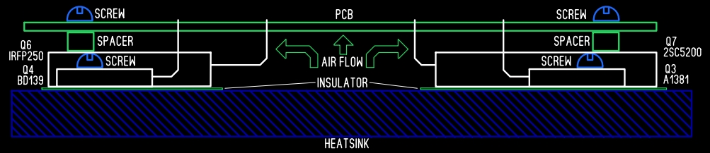
I think if the BD139 Vbe Multiplier is mounted on same heatsink next to MOSFET it's enough thermal coupling so doesn't need to sit on top of MOSFET anymore. But doing this allows the board to sit against the MOSFET and output BJT directly fora very secure mount. This would require smaller holes above the big output BJT and MOSFET so that the screw head can clamp against the PCB. For this reason making the holes smaller on these two is a good idea. Now no spacer is. needed.
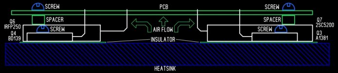
It is a good idea to use some form of spacer between the backside of the output transistors and the pcb to improve airflow and reduce the heat conduction into board mounted components. Having the thermal sensor mounted to the backside of an output also improves thermal tracking. This is how I lay out some of my boards and also how Hugh does it for his more recent designs.
You would still require spacers for the TO126 transistors, when they are mounted directly on the common heatsink. Thickness of TO3P, TOP3 packages is not the same as TO126.
The smaller ones don't have spacers and simply mount at level appropriate to be flush with heatsink. All mechanical stress is mainly through main output mount. True, a small non-thermally conductive spacer like a fiber or high temp plastic washer between main outputs and board would improve airflow and prevent direct conduction back to PCB. My gen 1 Prasi layout uses dead BD139 transistor as spacer and indeed the mounting of two main outputs provides plenty of mechanical stability for entire board.
")
I would put a wider spacer to insure mechanical strength, I prefer the diagram on post 409 although the above provide a better airflow.
http://www.diyaudio.com/forums/soli...-quasi-complimentary-mosfet-amplifier-41.html
BR,
Eric
http://www.diyaudio.com/forums/soli...-quasi-complimentary-mosfet-amplifier-41.html
BR,
Eric
Thanks for making those changes Dacz and this amp is going to be one of the notable greats as time goes by. It has a nice sound, is fairly easy to make, and now that the kinks of the initial issues of startup/setup have been worked out, should be an easy amp to build and use.
I've got some IRFP250 and 2SD1047. Would the latter be suitable for this project?
http://www.st.com/content/ccc/resou...df/jcr:content/translations/en.DM00026462.pdf
http://www.st.com/content/ccc/resou...df/jcr:content/translations/en.DM00026462.pdf
Last edited:
First time I have heard of 2SD1047. Looks like it has slightly lower current and dissipation rating, but should work. I don't know about other parameters like linearity though as it says for power supplies in application note rather than for audio amplifier.
Probably doesn't hurt to try it - maybe max power is a little less for safe operation.
Probably doesn't hurt to try it - maybe max power is a little less for safe operation.
Yes, both salvaged from old power supplies and UPS....as it says for power supplies in application note rather than for audio amplifier.
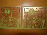
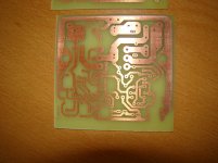
I've been lurking in the shadows on this thread since the start. Some very nice work has been done here. I etched a pair of boards this morning and I'll get on building them right away. Will report back when there is something to report...I'm not nearly as speedy as some folks here.
Thanks to all involved,
Evan
Thanks to all involved,
Evan
Attachments
- Home
- Amplifiers
- Solid State
- Very simple quasi complimentary MOSFET amplifier