Drivers and mosfets at 50°C steady
and what is your ambient temp?
It does sound very good at low levels but when output reaches 1vrms into eight ohm speakers it scratches hard.
Can the 1000u feedback cap be responsible by this ?
Presumably not. Anyway, replacing it by a lower value one doesn't take too much effort, does it?
Best regards!
Per device
Each one must be dissipating 15w idling. Heatsink now at 57°
Now it sounds full bodied with loads of detail and it lost the harshness ... bass is outstanding.... now fed by the DCG3 preamp without issues.
It still has a slight sizzle in the highs.... must increase current to 300mA per device.
Each one must be dissipating 15w idling. Heatsink now at 57°
Now it sounds full bodied with loads of detail and it lost the harshness ... bass is outstanding.... now fed by the DCG3 preamp without issues.
It still has a slight sizzle in the highs.... must increase current to 300mA per device.
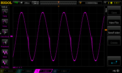
Do you still observe these bursts in the falling slopes, right after crossing the zero line?
As said elsewhere in this board, by swapping both the input and the output devices from BJT's to FET's, you've turned the amplifier into completely another one. Your scope clearly shows massive stability issues that cannot be resolved just by increasing bias. Now you may not take the compensation regime of the Honey Badger as-is, you need another one. Sadly I can't help you either, as I'm clearly no KOC (King of Compensation).
Best regards!
I agree with AJT on this point, make the CCS with matched fixed resistorsWill replace the mirror load resistors by fixed ones.
If anything the overly large capacitor might reduce distortion. But look at D.Self. His data seems to show that placing the NFB roll-off @ roughly 1/20th of the LF pass band reduces the in band distortion to negligible values. Few others have given us measured data.How does the 1000u affect distortion ?
You have a mixed AC & DC coupled arrangement, where the LF passband is not defined by an input filter. How do you determine the LF pass band?
Did you match your mosFETS at the operating current?one of the N mosfets is drawing much less current than the others... another issue to solve now
Did you match your source resistors at the operating current?
Doing both will give you a reasonable chance of seeing a closly matched set of currents and a reasonable chance of actually measuring the difference in those currents.
If your source resistors have a tolerance of +-10% how can you hope to measure currents with any confidence better than that +-10%?
Last edited:
Does this oscillation turn on as you pass above 0.8Vac at the input?Here is what I see in the scope when the amp is loaded by a speaker.
Input is 0.8v
But is invisible below 0.8Vac?
Does a low input voltage with various reactive loads promote any oscillation?
Have you tried stepping from 1nF through to 1uF at the speaker terminals?
decreasing the gain, may make this worse.Sounds slightly cleaner now but it "crackles" when I push the volume up to medium.
Allready increased input series resistance to 2k7 and it did not solve the issue.
It seems to overload to easily... gain is now 32dB with the feedback resistors 33k and 820 ohm.... should I increase feedback to lower gain ?
The feedback goes up as the gain goes down and that usually results in lower stability margins.
The little bit of overshoot in post127 confirms that compensation is not quite there yet.
You can go the other way as an experiment: increase the gain by paralleling the 820r with another. That reduces the feedback by 6dB.
If this clears the oscillation then it tells you the compensation needs further work to increase the stability margins. After that I can't help because this is the area where my lack of AC theory shows my limitations.
Overshoot is no sign of instability, and some topologies work best with a little overshoot. Ringing however is. Outright oscillation should not occur regardless of overshoot. Hopefully you are taking the square wave measurements without the RC filter.
Try tuning the compensation without R24 first, since it can introduce some overshoot and harmless response quirks at RF.
Crackling when the volume is changed probably means the amp is going in and out of oscillation as the pot change resistance to ground and resistance to source (sometimes grounding the input causes oscillation, or it can be the other way, there is oscillation if the input is not grounded - either way, it should be addressed either as local parasitic oscillation or by adjusting the global compensation). If you cannot find the oscillation on the scope it's possible it's in the hundreds of MHz and is probably parasitic oscillation of the input FETs. Your input is heavily filtered by the input RC, but it's also possible that interactions through the input ground could cause oscillation. If this is the case you may have to try changing grounding arrangements. For instance grounding the heatsink to the PCB through a 47R resistor is something that may help. Or changing the order of connections along the ground trace.
Your scope plot shows oscillation in the crossover region where the output stage is slower than normal. To me this suggests that C17 may be too large.
Do you have a picture of the PCB so we can see the layout?
Last edited:
Per device
Each one must be dissipating 15w idling. Heatsink now at 57°
Now it sounds full bodied with loads of detail and it lost the harshness ... bass is outstanding.... now fed by the DCG3 preamp without issues.
It still has a slight sizzle in the highs.... must increase current to 300mA per device.
good to know.....
in and around the 80's when yamaha and sony came up with Vfets amps,
it was mentioned in the Audio magazine article that at idle currents of 300mA or so, mosfet distortions are quite low...
quote low....
make the CCS with matched fixed resistors
yes this is doable, i suggested that the current mirror loads of the cascodes have
fixed emitter resistors....
Will doI agree with AJT on this point, make the CCS with matched fixed resistors
i do not know how to determine LF pass bandIf anything the overly large capacitor might reduce distortion. But look at D.Self. His data seems to show that placing the NFB roll-off @ roughly 1/20th of the LF pass band reduces the in band distortion to negligible values. Few others have given us measured data.
You have a mixed AC & DC coupled arrangement, where the LF passband is not defined by an input filter. How do you determine the LF pass band?
Did you match your mosFETS at the operating current?
Did you match your source resistors at the operating current?
Doing both will give you a reasonable chance of seeing a closly matched set of currents and a reasonable chance of actually measuring the difference in those currents.
If your source resistors have a tolerance of +-10% how can you hope to measure currents with any confidence better than that +-10%?
I matched the mosfets and the resistor I did using your suggested method. These are between 0.1012 and 0.1015 ohms.... Anyway this issue is now adressed as I found the difference in currents was due to oscilations while measuring.
I increased the capacitors between drain and gate of the output mosfets to 15p and now everything seems more stable
Does this oscillation turn on as you pass above 0.8Vac at the input?
But is invisible below 0.8Vac?
Does a low input voltage with various reactive loads promote any oscillation?
Have you tried stepping from 1nF through to 1uF at the speaker terminals?
The oscilation was visible only when input higher than 0.6Vac
I did not try purely reactive loads
i do not know how to determine LF pass band
this calculator can help you....Online RC Highpass filter Calculator | XY Calculator
- Status
- This old topic is closed. If you want to reopen this topic, contact a moderator using the "Report Post" button.
- Home
- Amplifiers
- Solid State
- Very HQ power amplifier (Assemblage VII)