After building the Assemblage power amp where I reached a new level of understanding related with power amp design, I decided to venture into a more powerful and hopefully higher performance machine.
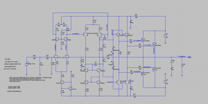
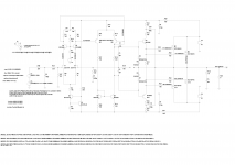
A lot of work was done searching for the ultimate design and after numerous simulations I have a preferred schematic based on the nimesis.
The final design can be found here: http://www.diyaudio.com/forums/soli...-amplifier-assemblage-vii-10.html#post5125837
A lot of work was done searching for the ultimate design and after numerous simulations I have a preferred schematic based on the nimesis.
The final design can be found here: http://www.diyaudio.com/forums/soli...-amplifier-assemblage-vii-10.html#post5125837
Attachments
Last edited:
Do I really need one driver per output lateral ?
Depending on desired slew rate, no. Have run two pairs of dual die laterals off one pair of bootstrapped BC560, BC550 transistors without problems.
Paul
Depending on desired slew rate, no. Have run two pairs of dual die laterals off one pair of bootstrapped BC560, BC550 transistors without problems.
Paul
Hi Paul
How close did you need to pair the laterals ?
Did you use Rs at all ?
Should I replace R17 by a suitable stiff ccs ?
Attachments
Hi Paul
How close did you need to pair the laterals ?
Did you use Rs at all ?
Was lazy and didn't match the laterals at all. Relied on the fact they came from the same batch and used 0.22R source resistors. Probably not optimal to skip the matching but the amp did work without issues.
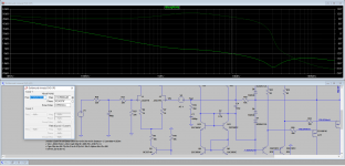
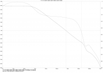
Have done a tian probe stability analysis of the GNFB loop.
Nice stability margins!
ULGF = 692 KHz
PM = 82 degrees
GM = 28 dB
Paul
Attachments
Last edited:
Was lazy and didn't match the laterals at all. Relied on the fact they came from the same batch and used 0.22R source resistors. Probably not optimal to skip the matching but the amp did work without issues.
So the Rs you used served as well to tame gain differences.... how does it sound with those highish Rs ?
Could not find a schematic for the telos.... can you help ?Hi
What is the difference with the Goldmund Telos 390?
Fab
So the Rs you used served as well to tame gain differences.... how does it sound with those highish Rs ?
Certainly didn't have any thermal problems. Sounded ok to me but then I would be biased towards my own design
")
Had a little play with your design....
Paul
Attachments
Last edited:
The schematic look like Goldmund Mimesis with current mirror improved (for more precision both side) and same as my amp what i did fews year ago. I have used 10pF MC caps for both side VAS/TIS.
However, this circuit also same as OPS of Golmund Telos, one driver for one output MOSFET. The Telos basically use higher LTP Iq (4.3mA for both side, lower LTP load), lower VAS Iq.
Try to use diff value of Rg, as Semelab recommended.
// I also use 0.1R (MPC74 0R1) for all Rs, MOSFETs don't share current, so a large resistance value don't help you to fix if mismatch MOSFET, my reason is easy to measure Iq of OPS.
Last edited:
Had a little play with your design....
Paul
Thank you very much Paul
Your mods lower some distortions but I do not fully understand them.
Why did you connect the LTP cascode bases to the output ?
That way you need a dedicated psu (V2) to bias the bases.....
Also... would you elaborate on your choice of boostrap on the drivers ?
Try to use diff value of Rg, as Semelab recommended.
.
What value would you use in this case ?
Thank you very much Paul
Your mods lower some distortions but I do not fully understand them.
Why did you connect the LTP cascode bases to the output ?
That way you need a dedicated psu (V2) to bias the bases.....
Also... would you elaborate on your choice of boostrap on the drivers ?
Hi,
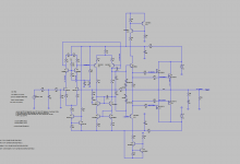
The LTP cascode is now driven. This keeps the voltage across your input FETs constant. The cascode voltage now follows the input signal.
The bootstrapping on the presents the VAS output with a much easier load to drive. The problem of the non-linear cob of the drivers is now removed (same with the LTP). It gives an added bonus of be able to use small fast transistors.
No need for a separate supply for the LTP cascode 15V see .asc
Paul
Attachments
Last edited:
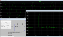
I believe we are getting near what I am looking for.
Appart from some artifacts I find in the FFT running your design, it seems really good.
Now I would like to avoid the bootstraps.... can we do it with ccs ? (I would like to avoid the EL caps signature.
I made a sim that does not work but maybe you could help me here.....
Appart from some artifacts I find in the FFT running your design, it seems really good.
Now I would like to avoid the bootstraps.... can we do it with ccs ? (I would like to avoid the EL caps signature.
I made a sim that does not work but maybe you could help me here.....
Attachments
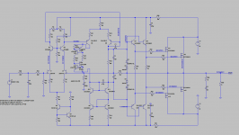
There may be some quirks in the version I posted. Was really to provide some "food for thought". It is your design....
To use CCS instead of the bootstraps you need folded drivers. In the .asc posted I have bootstrapped the collectors to the output again. But the collectors can be returned to the power rails instead. This would allow the use of the KSA1381/KSC3503 transistors. With the bootstrap in place you need to have transistors that work well at low Vce.
You need to consider the transistors in your lower current mirror - KSA1381/KSC3503 transistors will not be the best choice here.
One issue with the .asc is the bias current in the output devices. May be a little high?
Paul
Attachments
Last edited:
- Status
- This old topic is closed. If you want to reopen this topic, contact a moderator using the "Report Post" button.
- Home
- Amplifiers
- Solid State
- Very HQ power amplifier (Assemblage VII)