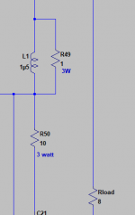
While testing the amp with a 2uF cap over the 8ohm output load I noticed severe ringing with a 20k square wave .... I am now aware it was the cap resonating with the output coil... so I reduced the output coil resistor to 1 ohm.
Maybe I should reduce it to 0.33ohm but I am not sure this is a good move.
Maybe I should reduce it to 0.33ohm but I am not sure this is a good move.
Attachments
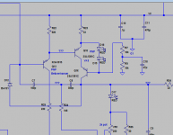
Still have doubts regarding an implementation suggested by Andrew...
According to his info I should place a diode over the feedback capacitor.... I guess that technique is used to limit the voltage seen by this cap so one can use a smaller lower voltage cap there ... but I am using a 1000u 25V bipolar in that placement so maybe there is no need for the diode.....
According to his info I should place a diode over the feedback capacitor.... I guess that technique is used to limit the voltage seen by this cap so one can use a smaller lower voltage cap there ... but I am using a 1000u 25V bipolar in that placement so maybe there is no need for the diode.....
Attachments
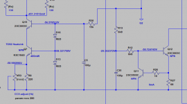
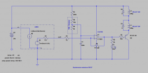
The amp does now have a softstart, a DC detection circuit and a temperature controlled relay that shuts it down if the heatsinks go higher than 70°C.
I also need a short circuit protection but do not like the typical current limiting circuits available so I asked Bonsai and he suggested the circuit present in his ovation e-amp that I am now studying.
The temperature control uses a LM35 and a CA3140 comparator set with slight hyteresis....
I also need a short circuit protection but do not like the typical current limiting circuits available so I asked Bonsai and he suggested the circuit present in his ovation e-amp that I am now studying.
The temperature control uses a LM35 and a CA3140 comparator set with slight hyteresis....
Attachments
Last edited:
if you have 10r in parallel to the output inductor and there is an HF signal passing to the load, then the inductor presents a high impedance and the 10r becomes the load.While testing the amp with a 2uF cap over the 8ohm output load I noticed severe ringing with a 20k square wave .... I am now aware it was the cap resonating with the output coil... so I reduced the output coil resistor to 1 ohm.
Maybe I should reduce it to 0.33ohm but I am not sure this is a good move.
That 10r load is in series with any capacitance either in the cables or in the speaker.
The PCB located Zobel (possibly 10r+100nF) and this extra 10r+?nF are effectively in parallel.
Thus the amplifier sees an HF load of 10r||10r, i.e. 5r
If you lower the inductor damping resistor to 5r, the amplifier now sees a 10r||5r = 3r3
Lower it to 1r and the amplifier sees 10r||1r ~ 0r9
Can you output stage drive sufficient current into this lowered load?
if you have 10r in parallel to the output inductor and there is an HF signal passing to the load, then the inductor presents a high impedance and the 10r becomes the load.
That 10r load is in series with any capacitance either in the cables or in the speaker.
The PCB located Zobel (possibly 10r+100nF) and this extra 10r+?nF are effectively in parallel.
Thus the amplifier sees an HF load of 10r||10r, i.e. 5r
If you lower the inductor damping resistor to 5r, the amplifier now sees a 10r||5r = 3r3
Lower it to 1r and the amplifier sees 10r||1r ~ 0r9
Can you output stage drive sufficient current into this lowered load?
thank you Andrew.... now I see the issue
I imagine you are worried for thermal runaway with that LED controlled bias, right?
What about the UPC1237? Is it reliable?
Marantz and Luxman used it.
The UPC1237 can be used to build a dc fault protection but I never saw a circuit using this chip to detect over current.
As for the LED, if it is exposed to an over current it will burn and open circuit... that will increase bias enormously and probably burn the OPS
- Status
- This old topic is closed. If you want to reopen this topic, contact a moderator using the "Report Post" button.
- Home
- Amplifiers
- Solid State
- Very HQ power amplifier (Assemblage VII)