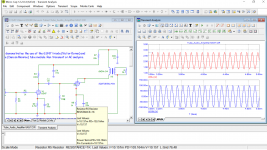
Here is update for 6AG7_GE, briefly tested ok in MicroCap.
Is there a straightforward way to modify these models to work properly in MicroCap? I've been using the 6DY7 model (that you so graciously provided) in LTspice without much trouble, but it triggers the same "floating point overflow" error that others are seeing in MicroCap.
I don't want to ask you to re-model it for me again, especially if there's a simple way to edit the model text.
Thanks!
Is there a straightforward way to modify these models to work properly in MicroCap?
You need Paint Tool Kit to modify it properly so that you can see how it looks like when you altering. If you know how to use it then you still need the original image curve. Once open you can paste the model file I posted and update it and edit the params under "Advance Knee" then tested with MicroCap. You can disable others to see if the error goes away. Sometimes change "Knee" to "Advance Knee" or "Kink" will work but the model will be out of fit so it is not so accurate any more.
I have all the data curves, here is 6DY7, if you want to go ahead. The other way is try to use Adrian's model see it solves your problem. I have tried but need to clean out so many comment lines that cause errors in MicroCap, unless he can provides a clean copy for testing it would be more affirmative.
Attachments
Last edited:
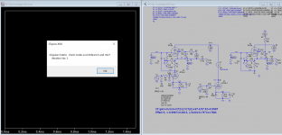
Sometimes not all error is caused by the model, it applied to circuit as well, there errors (or short circuit) in the upper Pentode circuit, the data shown is garbled with error message. This one is fixed by using ".options gminsteps=0"
Attachments
Last edited:
The other way is try to use Adrian's model see it solves your problem
Hi all,
here my approach for the 6AG7 model. I do not have MC on my Mac, so I could not test whether it works in MC. Just let me know.
merry Christmas!
Adrian
Code:
*6AG7 LTspice model based on the generic tetrode/pentode model from Adrian Immler, version i4, Dec 2020
*A version log is at the end of this file
*Params fitted to GE datasheet by Adrian Immler, Dec 2020
*This model is an enhancement of Adrians generic triode model to achieve tetrode/pentode behaviour.
*Hence, it is also suitable when the tetrode/pentode is "triode connected".
*Convenient for tetrodes, power beam tetrodes and g3-grounded pentodes.
*Copes secondary emission effect!
*            GE=General Electric Company
*            | version i4
*            | |  plate (in this model, "anode" means the internal virtual triode anode)
*            | |  | grid2
*            | |  | |  grid1
*            | |  | |  |  cathode
*            | |  | |  |  |
.subckt 6AG7.GEi4 P G2 G1 K
+ params:
*Parameters for the space charge current @ Vg <= 0
+ mu1 = 25.6    ;Main factor for voltage gain @ constant Ia in triode mode
+ ks = 205      ;Permeance factor. Has to be readjusted if xs is changed
+ Vg0 = 0.75    ;Offsets the Ia-traces on the Va axis. Electrode material's contact potential
+ kp = 140      ;Mimics the island effect
+ xs = 1.5      ;Determines the curve of the Ia traces. Typically between 1.2 and 1.8
*
*Parameters for an optional space charge current reduction @ Vg > 0
+ kIsr = 0.03   ;Va independable Is reduction, a function of Vg1
+ Rg1i = 100    ;Internal grid1 resistor which causes an extra Is drop when Va approaches zero.
*
*Parameters for assigning the space charge current to Ia and Ig @ Vg > 0 and small Va
+ kB1 = 0.1     ;Describes how fast Ia_virtual drops to zero when Va_virtual approaches zero.
+ radl = 950    ;Differential resistance for the Ia emission limit @ very small Va and Vg > 0
+ tsh = 10      ;Ia transmission sharpness from 1th to 2nd Ia area. Keep between 3 and 20. Start with 20.
+ xl = 0.91     ;Exponent for the emission limit
+ Vctl = 0 f=0  ;Offsets the Ia emission limit trace on the Va axis. f=related Vg1 koeff.
*
*Parameters of the grid-cathode vacuum diode
+ kg1 = 1k55    ;estimated value!!
+ Vctg1 = 0.55  ;estimated value!!
+ xg1 = 1.5     ;Determines the curve of the Ig slope versus (positive) Vg and Va >> 0
+ VT = 0.1      ;Log(Ig) slope @ Vg<0. VT=k/q*Tk (cathodes absolute temp, typically 1150K)
*
*Parameters for the caps
+ cg1p  = 0p06  ;according GE datasheet
+ cg1All= 13p   ;according GE datasheet
+ CpAll = 7p5   ;according GE datasheet
+ Cpk   = 0p1   ;not mentioned in datasheet
*
*Parameters to enhance the triode model to a pentode model
+ mu2 = 70      ;1/mu2 is the fraction of Vp which together with Vg2i builds the virtual Triode-Anode Voltage
+ kB2 = 0.2     ;Describes how fast Ip drops to zero when Vp approaches zero.
+ Rg2i = 100    ;Internal grid2 resistor. Causes an Is reduction when Ig2 increases while Vp drops
+ fr2 = 0.195   ;determines the residual ig2 fraction @ high Va values
+ ftfr2 = 0m7   ;if fr2 showes a Vg2 dependancy, this can be considered with this parameter
*
*Parameters to mimic the secondary emission (inspired from Derk Reefmans approach)
+ co = 1.4      ;decribes the crossover region (Ise drop when Va increase). between 0 and 9
+ Vse=60   a=0  ;Va where the sec. emission is strongest. a=related Vg1 coefficient
+ Ise0=0 b=0    ;sec. emission peak current @ Vg=0. b=related Vg1 coefficient
+ Vg2ref = 250  ;Vg2 where the following coeffficients has no influence to the emission effect:
+ c = 0         ;Vg2 coefficient of a
+ d = 0         ;exp Vg2 coefficient of Ise0
+ e = 0         ;Vg2 coeff. of b
*
*Calculated parameters
+ kl = pow(1/(radl*xl*Ild**(1-1/xl)),-xl) ;Reduces the xl influence to the Ia slope @ small Va
+ Ild = sqrt(radl)*1m ;Current where the limited anode a.c. resistance is set according to radl.
*
*Space charge current model
Bggi GG1i 0 V=v(G1i,K)+Vg0 - v(G1,K)*(1-1/(1+kIsr*max(0,v(G1,K)))) ;Effective internal grid voltage.
Bahc Ahc 0 V=uramp(v(P,K)/mu2+v(G2i,K)) ;voltage of the virtual triode anode, hard cut to zero
Bst St 0 V=max(v(GG1i)+v(Ahc)/(mu1), v(Ahc)/kp*ln(1+exp(kp*(1/mu1+v(GG1i)/(1+v(Ahc))))));Steering volt.
Bs Ai K I=1/ks*pow(v(St),xs) ;Langmuir-Childs law for the space charge current Is
*
*Anode current limit @ small Va
.func smin(w,y,n) {pow(pow(w + 1f, -n)+pow(y+1f, -n), -1/n)} ;Min-function with smooth trans.
Ra A Ai 1
Bpl G2i P I=i(Rp) - smin(1/kl*pow(v(P,K)+min(0,Vctl+f*v(G1,K)),xl),i(Rp),tsh);Ip emission limit
*
*Grid model
Rg1i G1 G1i {Rg1i} ;Internal grid resistor for "Ia-reduction" @ Vg > 0
.func Ivd(Vvd, kvd, xvd, VTvd) {1/kvd*pow(VTvd*xvd*ln(1+exp(Vvd/VTvd/xvd)),xvd)} ;Vacuum diode function
Bg1vd G1 K I=Ivd(v(G1,K)+Vctg1-1m*sqrt(v(Ahc)), kg1, xg1, VT) ;Grid-cathode vacuum diode
Bg1r G1i Ai I=ivd(v(GG1i),ks, xs, 0.8*VT)/(1+kB1*v(Ahc));Is reflection to grid when Va appr. zero
Bs0 Ai K I=ivd(v(GG1i),ks, xs, 0.8*VT) - 1/ks*pow(v(GG1i),xs) ;Compensates neg Ia
*@ small Va and Vg near zero
*
*additional model parts necessary for a pentode
Rg2i G2 G2i {Rg2i}
Rp P A 1
Bg2r G2i A I=i(Ra)*((1-frg2())/(1+kB2*max(0,v(P,K))) ) ; Va dependable ig2 part, reflected from the plate
Bg2f G2  A I=i(Ra)*frg2() ; Va independable ig2 part. Not to lead this current over Rg2i improves convergence
.func frg2() {fr2*exp(ftfr2*(v(G2,K)-300))}
*
*model for secondary emission effect
*nomalizing function nf(sh) ensures that the peak of y=x*(1-tanh(sh(x-1)) is always at x=1 while sh=0..9
;.func nf(z) {609m/z + 293m + 107m*z - 5.71m*z*z}
;.func sh() {pow(co,2)} ;results in a more linear control of the cross over region with the param co
;Bsee G2 P I=min(Ise()*nf(sh())*xf()*(1-tanh(sh()*(nf(sh())*xf()-1))) / (nf(sh())*(1-tanh(sh()*(nf(sh())-1)))),i(Rp)-i(Bpl))
;.func Ise() {smin(uramp(Isef() - bf()*v(G1,K)),0.98*i(Rp),2)} ;avoides neg. Iplate caused by strong sec. em.
;.func xf() {v(P,K)/(1m+uramp(Vse-af()*v(G1,K)))}; moves the sec emission peak to the wanted voltage Vsep
;.func af() {a + c*(v(G2,K)-Vg2ref)}
;.func Isef()   {Ise0 * exp(d*(v(G2,K)-Vg2ref))}
;.func bf()  {b + e*((v(G2,K)-Vg2ref))}
*
*Caps
C1 G1 P {cg1p}
C2 G1 K {(cg1All-cg1p)/2} ;As this model does not consider the ambient as further electrodes for parasitic caps,
;best way is to assume this " g1 to all" cap as it would be half to cathode and half to g2 (after substraction of cg1p).
C3 G1 G2 {(cg1All-cg1p)/2}
C4 P K {cpk}
C5 P G2 {cpAll-cpk-cg1p}
.ends
*
*Version log
*i1 :Initial version
*i2 :Pin order changed to the more common order "P G2 G1 K" (Thanks to Markus Gyger for his tip)
*i3 :residual ig2 @ large Va introduced; 2nd emission effect introduced;
;Va indep. grid current parts no longer lead over internal grid resistors for better convergence
*i4 :to improve convegence, the Ia reduction @ pos Vg is no longer done by Rg1i. Instead, kIsr introduced
;Furthermore, ks and Vg0 are set directly, as rad and Vct turned out to be usefull for triodes only
*i4f :Major bug fixed. Tube works now also when Cathode not grounded (for cathode follower and the like)
Attachments
Unfortunately it still gives me errors (Part and node have the same name X1 G2)
Yes, that is a only warning, it will continue to sim. Some are real errors like "Matrix is singular", I can't solve it, and it also appears in LTspice. These models using "Advance Knee" options is a little too much for Spice program to handle as explained in the errors messages of MicroCap.
It continues to sim (really there is no possibility to use the Probe), but it gives busted values anyway...
it seems that all the nodes are the same.
Last edited:
I got the same warning but data appears ok. The following my .Option file:
Model file:
Code:
.OPTIONS ACCT LIST OPTS ABSTOL=1pA CHGTOL=.01pC DEFL=100u DEFW=100u DEFNRD=0
+ DEFNRS=0 DEFPD=0 DEFPS=0 DIGDRVF=2 DIGDRVZ=20K DIGERRDEFAULT=20 DIGERRLIMIT=0
+ DIGFREQ=10GHz DIGINITSTATE=0 DIGIOLVL=2 DIGMNTYMX=2 DIGMNTYSCALE=0.4
+ DIGOVRDRV=3 DIGTYMXSCALE=1.6 DIODE_MAX_IS=1e-6 GMIN=1p INTERPOLATION_ORDER=2
+ ITL1=250 ITL2=50 ITL4=10 PIVREL=1 PIVTOL=.1p RELTOL=1m SANDH_PRECISION=1e-4
+ SD=2.58 SEED=0 TEMP=27 TNOM=27 TRTOL=7 VNTOL=1u WIDTH=80 PRIVATEDIGITAL=0
+ PRIVATEANALOG PERFORM_M=2 RMIN=1u R_NODE_GND=1e12 PATH_TO_GROUND
+ VOLTAGE_LOOP_CHECK FLOATING_NODES_CHECK=0 NUMERIC_DERIVATIVE=0 LTHRESH=1.5
 + LONE=3.5 LZERO=.3 CSHUNT=0 RSHUNT=0 RP_FOR_ISOURCE=0 METHOD=TRAP
Model file:
Code:
**** 6AG7_GE ******************************************
* Created on 12/15/2020 21:01 using paint_kip.jar
* [url=http://www.dmitrynizh.com/tubeparams_image.htm]Model Paint Tools: Trace Tube Parameters over Plate Curves, Interactively[/url]
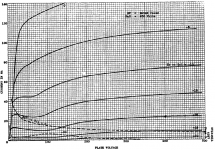
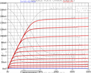
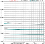
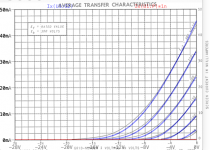
* Plate Curves image file: 6ag7-ge.png
* Data source link: <plate curves URL>
*----------------------------------------------------------------------------------
**** 6AG7_GE ******************************************
* Created on 12/17/2020 15:35 using paint_kip.jar
* [url=http://www.dmitrynizh.com/tubeparams_image.htm]Model Paint Tools: Trace Tube Parameters over Plate Curves, Interactively[/url]
* Plate Curves image file: 6ag7-GE.png
* Data source link: <plate curves URL>
*----------------------------------------------------------------------------------
.SUBCKT 6AG7_GE P G2 G K ; LTSpice tetrode.asy pinout
* .SUBCKT 6AG7_GE P G K G2 ; Koren Pentode Pspice pinout
+ PARAMS: MU=25.85 KG1=510.98 KP=148.26 KVB=5167.75 VCT=0.572 EX=1.296 KG2=360.85 KNEE=16582.14 KVC=1.884
+ KLAM=2E-9 KLAMG=6.874E-5 KD=0.03952 KC=0.4435 KR1=4.56E-4 KR2=0.00104 KVBG=3.267E-4 KB1=3.564 KB2=3.474 KB3=2 KB4=0.264 KVBGI=0.001536 KNK=-0.8761 KNG=0.2739 KNPL=7.016 KNSL=75.98 KNPR=64.46 KNSR=100.61
+ CCG=3P CGP=1.4P CCP=1.9P VGOFF=-0.9 IGA=1.4E-4 IGB=0.069 IGC=13.2 IGEX=1.32
* Vp_MAX=500 Ip_MAX=200 Vg_step=2 Vg_start=8 Vg_count=15
* X_MIN=36 Y_MIN=28 X_SIZE=727 Y_SIZE=592 FSZ_X=1296 FSZ_Y=736 XYGrid=false
* Rp=1400 Vg_ac=20 P_max=9 Vg_qui=-6 Vp_qui=300
* showLoadLine=n showIp=y isDHP=n isPP=n isAsymPP=n isUL=n showDissipLimit=y
* showIg1=y isInputSnapped=y addLocalNFB=n
* XYProjections=n harmonicPlot=y dissipPlot=n
* UL=0.43 EG2=150 gridLevel2=y addKink=y isTanhKnee=n advSigmoid=y
*----------------------------------------------------------------------------------
RE1 7 0 1G ; DUMMY SO NODE 7 HAS 2 CONNECTIONS
E1 7 0 VALUE= ; E1 BREAKS UP LONG EQUATION FOR G1.
+{V(G2,K)/KP*LOG(1+EXP((1/MU+(VCT+V(G,K))/SQRT(KVB+V(G2,K)*V(G2,K)))*KP))}
RE2 6 0 1G ; DUMMY SO NODE 6 HAS 2 CONNECTIONS
E2 6 0 VALUE={(PWR(V(7),EX)+PWRS(V(7),EX))} ; Kg1 times KIT current
E4 8 0 VALUE={V(P,K)/KNEE/(KVBGI+V(6)*KVBG)}
E5 81 0 VALUE={PWR(V(8),KB1)}
E6 82 0 VALUE={PWR(V(8),KB2)}
E7 83 0 VALUE={PWR(V(8),KB3)}
E8 9 0 VALUE={PWR(1-EXP(-V(81)*(KC+KR1*V(82))/(KD+KR2*V(83))),KB4)*1.5708}
RE4 8 0 1
RE5 81 0 1
RE6 82 0 1
RE7 83 0 1
RE8 9 0 1
RE21 21 0 1
E21 21 0 VALUE={V(6)/KG1*V(9)} ; Ip with knee but no slope and no kink
RE22 22 0 1 ; E22: kink curr deviation for plate
E22 22 0 VALUE={V(21)*LIMIT(KNK-V(G,K)*KNG,0,0.3)*(-ATAN((V(P,K)-KNPL)/KNSL)+ATAN((V(P,K)-KNPR)/KNSR))}
G1 P K VALUE={V(21)*(1+KLAMG*V(P,K))+KLAM*V(P,K) + V(22)}
G2 G2 K VALUE={V(6)/KG2*(KVC-V(9))/(1+KLAMG*V(P,K)) - V(22)}
RCP P K 1G ; FOR CONVERGENCE
C1 K G {CCG} ; CATHODE-GRID 1
C2 G P {CGP} ; GRID 1-PLATE
C3 K P {CCP} ; CATHODE-PLATE
RE23 G 0 1G
GG G K VALUE={(IGA+IGB/(IGC+V(P,K)))*(MU/KG1)*
+(PWR(V(G,K)-VGOFF,IGEX)+PWRS(V(G,K)-VGOFF,IGEX))}
.ENDSAttachments
Last edited:
Hi all,
here my approach for the 6AG7 model. I do not have MC on my Mac, so I could not test whether it works in MC. (...)
Hi all,
yesterday I went through the springs post, where we discussed MC compatible spice code. I found #2289 as a good summary of the points to be considered.
I learned that my 6AG7 model posted in #2707 will not work in MC, as curly brackets are missed for the expression in the calculated expression section. The following adaptions are needed:
+ kl = {pow(1/(radl*xl*Ild**(1-1/xl)),-xl)}
+ Ild = {sqrt(radl)*1m}
cheers, Adrian
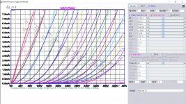
Hi people, happy holidays to all of you! I tried to make 6N17B-V model using triode paint tools. I know this is far from perfect, but after two hours of clicking and tweaking, I can't make it better. Any help appreciated. ")
Code:
.SUBCKT 6N17B_V 1 2 3 ; Plate Grid Cathode
+ PARAMS: CCG=3P  CGP=1.4P CCP=1.9P RGI=2000
+ MU=87 KG1=1196 KP=277.2 KVB=418.6 VCT=0.0122 EX=1.996
* Vp_MAX=480 Ip_MAX=8 Vg_step=0.5 Vg_start=1 Vg_count=13
* Rp=4000 Vg_ac=55 P_max=0.9 Vg_qui=-48 Vp_qui=300
* X_MIN=307 Y_MIN=240 X_SIZE=1303 Y_SIZE=849 FSZ_X=2578 FSZ_Y=1458 XYGrid=true
* showLoadLine=y showIp=y isDHT=n isPP=n isAsymPP=n showDissipLimit=y
* showIg1=n gridLevel2=n isInputSnapped=n
* XYProjections=n harmonicPlot=n dissipPlot=n
*----------------------------------------------------------------------------------
E1 7 0 VALUE={V(1,3)/KP*LOG(1+EXP(KP*(1/MU+(VCT+V(2,3))/SQRT(KVB+V(1,3)*V(1,3)))))}
RE1 7 0 1G  ; TO AVOID FLOATING NODES
G1 1 3 VALUE={(PWR(V(7),EX)+PWRS(V(7),EX))/KG1}
RCP 1 3 1G   ; TO AVOID FLOATING NODES
C1 2 3 {CCG} ; CATHODE-GRID
C2 2 1 {CGP} ; GRID=PLATE
C3 1 3 {CCP} ; CATHODE-PLATE
D3 5 3 DX ; POSITIVE GRID CURRENT
R1 2 5 {RGI} ; POSITIVE GRID CURRENT
.MODEL DX D(IS=1N RS=1 CJO=10PF TT=1N)
.ENDS
*$
Attachments
Hi rankot,
I guess You will not achieve a better result with another tool - because you want to fit your model to soviet datasheet, which is just „an indication“ but not more. My experience is, that fitting to measured data (e.g. UTracer or so) is much easier to fit.
This is in general the case, but especially for soviet tubes (the soviet tubes itself are mostly of good quality, manufacturing tolerances as close or even a bit better than west tubes, but the curves in the soviet datasheets are not as good as those from the West, especially german datasheets)
Cheers, Adrian
Koonw,
you misunderstand my last post.
Let explain me with other words.
I guess we all agree, that the 5 parameter Koren model delivers good results for plate current for standard triodes (sharp cutoff triodes, not remote cutoff versions). This is proven with a huge amount of good fitting results.
My personal experience is that the soviet data sheet curves are often not so close to reality (e.g. too bendy curves for the 6N3P, compared to measured curves from real samples). Therefore, fitting to such "not so real" data sheet curves may be a hard job and deliver not best accuracy - which seems logical to me.
But yes of course, the more parameters, the more flexible the model is.
cheers, Adrian
Hi people, happy holidays to all of you! I tried to make 6N17B-V model using triode paint tools. I know this is far from perfect, but after two hours of clicking and tweaking, I can't make it better. Any help appreciated.
Code:.SUBCKT 6N17B_V 1 2 3 ; Plate Grid Cathode + PARAMS: CCG=3P CGP=1.4P CCP=1.9P RGI=2000 + MU=87 KG1=1196 KP=277.2 KVB=418.6 VCT=0.0122 EX=1.996 * Vp_MAX=480 Ip_MAX=8 Vg_step=0.5 Vg_start=1 Vg_count=13 * Rp=4000 Vg_ac=55 P_max=0.9 Vg_qui=-48 Vp_qui=300 * X_MIN=307 Y_MIN=240 X_SIZE=1303 Y_SIZE=849 FSZ_X=2578 FSZ_Y=1458 XYGrid=true * showLoadLine=y showIp=y isDHT=n isPP=n isAsymPP=n showDissipLimit=y * showIg1=n gridLevel2=n isInputSnapped=n * XYProjections=n harmonicPlot=n dissipPlot=n *---------------------------------------------------------------------------------- E1 7 0 VALUE={V(1,3)/KP*LOG(1+EXP(KP*(1/MU+(VCT+V(2,3))/SQRT(KVB+V(1,3)*V(1,3)))))} RE1 7 0 1G ; TO AVOID FLOATING NODES G1 1 3 VALUE={(PWR(V(7),EX)+PWRS(V(7),EX))/KG1} RCP 1 3 1G ; TO AVOID FLOATING NODES C1 2 3 {CCG} ; CATHODE-GRID C2 2 1 {CGP} ; GRID=PLATE C3 1 3 {CCP} ; CATHODE-PLATE D3 5 3 DX ; POSITIVE GRID CURRENT R1 2 5 {RGI} ; POSITIVE GRID CURRENT .MODEL DX D(IS=1N RS=1 CJO=10PF TT=1N) .ENDS *$
I increased the Mu to (100+) get better fit. In circuit, the Mu is less (60-88)
Code:
**** 6N17B ******************************************
* Created on 12/29/2020 00:08 using paint_kit.jar 3.1
* [URL="http://www.dmitrynizh.com/tubeparams_image.htm"]www.dmitrynizh.com/tubeparams_image.htm[/URL]
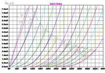
* Plate Curves image file: 6n17b.jpg
* Data source link:
*----------------------------------------------------------------------------------
.SUBCKT TRIODE_6N17B 1 2 3 ; Plate Grid Cathode
+ PARAMS: CCG=3P CGP=1.4P CCP=1.9P RGI=2201.8
+ MU=118.33 KG1=403.77 KP=268.35 KVB=1890.09 VCT=-0.3687 EX=1.358
* Vp_MAX=480 Ip_MAX=8 Vg_step=0.5 Vg_start=1 Vg_count=13
* Rp=4000 Vg_ac=55 P_max=40 Vg_qui=-48 Vp_qui=300
* X_MIN=76 Y_MIN=42 X_SIZE=781 Y_SIZE=513 FSZ_X=1296 FSZ_Y=736 XYGrid=false
* showLoadLine=n showIp=y isDHT=n isPP=n isAsymPP=n showDissipLimit=y
* showIg1=y gridLevel2=n isInputSnapped=n
* XYProjections=n harmonicPlot=n dissipPlot=n
*----------------------------------------------------------------------------------
E1 7 0 VALUE={V(1,3)/KP*LOG(1+EXP(KP*(1/MU+(VCT+V(2,3))/SQRT(KVB+V(1,3)*V(1,3)))))}
RE1 7 0 1G ; TO AVOID FLOATING NODES
G1 1 3 VALUE={(PWR(V(7),EX)+PWRS(V(7),EX))/KG1}
RCP 1 3 1G ; TO AVOID FLOATING NODES
C1 2 3 {CCG} ; CATHODE-GRID
C2 2 1 {CGP} ; GRID=PLATE
C3 1 3 {CCP} ; CATHODE-PLATE
D3 5 3 DX ; POSITIVE GRID CURRENT
R1 2 5 {RGI} ; POSITIVE GRID CURRENT
.MODEL DX D(IS=1N RS=1 CJO=10PF TT=1N)
.ENDSAttachments
Hi, I'm asking information to JJ about their KT77, but I find alot of resistance from them.
Is there anyonehere who has got curves of those specific tubes? I would like to run them in PP UL
JJ Electronic has KT77 tube data on their website, along with a download link for the PDF datasheet:
JJ Electronic - KT77
If you are looking for a SPICE model as opposed to the datasheet, here is one using the Ayumi model:
Vacuum Tube SPICE Models
- Home
- Amplifiers
- Tubes / Valves
- Vacuum Tube SPICE Models