Thanks for this information. Does Derk plan to also update the library file on his website (link below) or do we need to do this on our own?
We did not talk about this, but looking at the library I see it contains only the parameter values, the user must append the appropriate model (eg BTetrodeDE, BTetrodeD....) so I guess you have to do this on your own...
the parameters don't need to be changed it is only the mathematical G2 expression in the second .SUBCKT part of the .cir file that needs to be changed.
I noticed some other G2 definitions that did not match either of the ones you cited.
The two G2 equations apply to the BTetrodeDE and BTetrodeD models for ExtractModel V3.0; I have not looked at others such as as heptodes etc.
See attached .cir files as ExtractModel currently outputs them.
Attachments
Last edited:
Derk did the pioneer work to mimic secondary emission in spice. Up to now, there exists only 3 approaches able to cope secondary emission:
- Derk's
- my approach
- Dmitry's
Mine is an improved version of Derk's, providing independent parameters (so the tuning is less iterative) and also introduces ways to mimic Vg1 and Vg2 dependencies.
cheers, Adrian
- Derk's
- my approach
- Dmitry's
Mine is an improved version of Derk's, providing independent parameters (so the tuning is less iterative) and also introduces ways to mimic Vg1 and Vg2 dependencies.
cheers, Adrian
See attached .cir files as ExtractModel currently outputs them.
Thanks for these updates. I noticed that these two files contain a model for the same EH_6550_200. Which of the two models (BTetrodeD or BTetrodeDE) would you consider to be better for the 6550?
The BTetrodeDE model is the better choice for the 6550. The DERKE model was developed to improve the fit for beam power tetrodes.
Although the BTetrodeD model can be made to fit, some of the parameters become unrealistic (but the final simulation may be very similar to the BTetrodeDE)
BTW I would not recommend using the models I attached, they are based on uTracer measurements of one of a batch of 4 'matched' Electro-harmonix tubes I purchased, that turned out to have a fairly large spread and quite different from OEM manufacturer's data.
We did not talk about this, but looking at the library I see it contains only the parameter values, the user must append the appropriate model (eg BTetrodeDE, BTetrodeD....) so I guess you have to do this on your own...
the parameters don't need to be changed it is only the mathematical G2 expression in the second .SUBCKT part of the .cir file that needs to be changed.
I now noticed the TubeLib.inc library contains the BTetrodeD and BTetrodeDE .SUBCKT so I have taken the liberty of editing lines 1980 and 2001 to include the secondary emission term V(9)*KG2
The file is attached as a .txt, just change that to .inc for LTSpice
This is an unofficial edit, use at your own risk!
Attachments
The BTetrodeDE model is the better choice for the 6550. The DERKE model was developed to improve the fit for beam power tetrodes.
Although the BTetrodeD model can be made to fit, some of the parameters become unrealistic (but the final simulation may be very similar to the BTetrodeDE).
Very useful information. Thanks!
SRS-551 pentode and triode models here: SRS551 Pentode Curves and Model – Bartola(R) Valves
Enjoy, Ale
Enjoy, Ale

Error: Floating point 'overflow' (0xc0000091)
Status Bar Text: Preparing the DC analysis matrix.
Stack:
gettotal
c=110 * ti=0
Part: X1.G1
File: C:\MC12demo\DATA\circuit1.cir
.Subckt: X1 calls 6AG7_GE
Got the above errors in MicroCap when run in Transient, but no error with KT150 also model the same way. Maybe I remodel both models to see if I get rid of the error
Follow this video it tells how to import Paint Tool model to MicroCap, normal nothing need to be changed if import correctly.
Vacuum tube paint kit SPICE model generation and MicroCAP SPICE simulator - YouTube
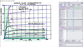
Here is 6AG7_RCA model, have briefly tried Transient in MicroCap it runs:\
Code:
**** 6AG7_RCA ******************************************
* Created on 12/17/2020 12:58 using paint_kip.jar
* [url=http://www.dmitrynizh.com/tubeparams_image.htm]Model Paint Tools: Trace Tube Parameters over Plate Curves, Interactively[/url]
* Plate Curves image file: 6ag7_rca.png
* Data source link: <plate curves URL>
*----------------------------------------------------------------------------------
.SUBCKT 6AG7_RCA P G2 G K ; LTSpice tetrode.asy pinout
* .SUBCKT 6AG7_RCA P G K G2 ; Koren Pentode Pspice pinout
+ PARAMS: MU=25.53 KG1=946.02 KP=96.43 KVB=339.84 VCT=0.572 EX=1.528 KG2=430.5 KNEE=3070.77 KVC=1.795
+ KLAM=2E-9 KLAMG=3.687E-4  KD=0.1257 KC=1.232 KR1=3.965E-4 KR2=0.00104 KVBG=4.219E-4 KB1=1.29 KB2=3.44 KB3=2 KB4=1.63 KVBGI=0.0048 KNK=-1.109 KNG=0.1999 KNPL=5.197 KNSL=123.55 KNPR=54.17 KNSR=61.35
+ CCG=13P CGP=0.06P CCP=7.5P VGOFF=-0.9 IGA=1.4E-4 IGB=0.069 IGC=13.2 IGEX=1.32
* Vp_MAX=500 Ip_MAX=160 Vg_step=2 Vg_start=0 Vg_count=9
* X_MIN=72 Y_MIN=59 X_SIZE=698 Y_SIZE=551 FSZ_X=1389 FSZ_Y=789 XYGrid=false
* Rp=1400 Vg_ac=20 P_max=9 Vg_qui=-8 Vp_qui=300
* showLoadLine=n showIp=y isDHP=n isPP=n isAsymPP=n isUL=n showDissipLimit=y
* showIg1=y isInputSnapped=y addLocalNFB=n
* XYProjections=n harmonicPlot=y dissipPlot=n
* UL=0.43 EG2=300 gridLevel2=y addKink=y isTanhKnee=n advSigmoid=y
*----------------------------------------------------------------------------------
RE1  7 0  1G    ; DUMMY SO NODE 7 HAS 2 CONNECTIONS
E1   7 0  VALUE=  ; E1 BREAKS UP LONG EQUATION FOR G1.
+{V(G2,K)/KP*LOG(1+EXP((1/MU+(VCT+V(G,K))/SQRT(KVB+V(G2,K)*V(G2,K)))*KP))}
RE2  6 0  1G    ; DUMMY SO NODE 6 HAS 2 CONNECTIONS
E2  6 0  VALUE={(PWR(V(7),EX)+PWRS(V(7),EX))} ; Kg1 times KIT current
E4   8 0  VALUE={V(P,K)/KNEE/(KVBGI+V(6)*KVBG)}
E5  81 0  VALUE={PWR(V(8),KB1)}
E6  82 0  VALUE={PWR(V(8),KB2)}
E7  83 0  VALUE={PWR(V(8),KB3)}
E8   9 0  VALUE={PWR(1-EXP(-V(81)*(KC+KR1*V(82))/(KD+KR2*V(83))),KB4)*1.5708}
RE4  8 0  1
RE5 81 0  1
RE6 82 0  1
RE7 83 0  1
RE8  9 0  1
RE21 21 0 1
E21  21 0 VALUE={V(6)/KG1*V(9)} ; Ip with knee but no slope and no kink
RE22 22 0 1 ; E22: kink curr deviation for plate
E22  22 0 VALUE={V(21)*LIMIT(KNK-V(G,K)*KNG,0,0.3)*(-ATAN((V(P,K)-KNPL)/KNSL)+ATAN((V(P,K)-KNPR)/KNSR))}
G1   P K  VALUE={V(21)*(1+KLAMG*V(P,K))+KLAM*V(P,K) + V(22)}
G2   G2 K  VALUE={V(6)/KG2*(KVC-V(9))/(1+KLAMG*V(P,K)) - V(22)}
RCP  P K  1G     ; FOR CONVERGENCE
C1   K G  {CCG}  ; CATHODE-GRID 1
C2   G P  {CGP}  ; GRID 1-PLATE
C3   K P  {CCP}  ; CATHODE-PLATE
RE23 G 0 1G
GG G K VALUE={(IGA+IGB/(IGC+V(P,K)))*(MU/KG1)*
+(PWR(V(G,K)-VGOFF,IGEX)+PWRS(V(G,K)-VGOFF,IGEX))}
.ENDS
*$
Attachments
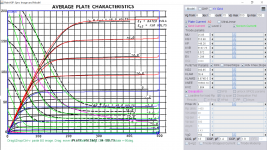
Here is update for 6AG7_GE, briefly tested ok in MicroCap.
Code:
*** 6AG7_GE ******************************************
* Created on 12/17/2020 15:47 using paint_kip.jar
* [url=http://www.dmitrynizh.com/tubeparams_image.htm]Model Paint Tools: Trace Tube Parameters over Plate Curves, Interactively[/url]
* Plate Curves image file: 6ag7-GE.png
* Data source link: <plate curves URL>
*----------------------------------------------------------------------------------
.SUBCKT 6AG7_GE P G2 G K ; LTSpice tetrode.asy pinout
* .SUBCKT 6AG7_GE P G K G2 ; Koren Pentode Pspice pinout
+ PARAMS: MU=25.85 KG1=510.98 KP=148.26 KVB=5167.75 VCT=0.572 EX=1.296 KG2=360.85 KNEE=16582.14 KVC=1.884
+ KLAM=2E-9 KLAMG=6.874E-5  KD=0.03952 KC=0.4435 KR1=4.56E-4 KR2=0.00104 KVBG=3.267E-4 KB1=3.564 KB2=3.474 KB3=2 KB4=0.264 KVBGI=0.001536 KNK=-0.8761 KNG=0.2739 KNPL=7.016 KNSL=75.98 KNPR=64.46 KNSR=100.61
+ CCG=13P CGP=1.4P CCP=1.9P VGOFF=-0.9 IGA=1.4E-4 IGB=0.069 IGC=13.2 IGEX=1.32
* Vp_MAX=500 Ip_MAX=200 Vg_step=2 Vg_start=8 Vg_count=15
* X_MIN=36 Y_MIN=28 X_SIZE=727 Y_SIZE=592 FSZ_X=1296 FSZ_Y=736 XYGrid=false
* Rp=1400 Vg_ac=20 P_max=9 Vg_qui=-6 Vp_qui=300
* showLoadLine=n showIp=y isDHP=n isPP=n isAsymPP=n isUL=n showDissipLimit=y
* showIg1=y isInputSnapped=y addLocalNFB=n
* XYProjections=n harmonicPlot=y dissipPlot=n
* UL=0.43 EG2=150 gridLevel2=y addKink=y isTanhKnee=n advSigmoid=y
*----------------------------------------------------------------------------------
RE1  7 0  1G    ; DUMMY SO NODE 7 HAS 2 CONNECTIONS
E1   7 0  VALUE=  ; E1 BREAKS UP LONG EQUATION FOR G1.
+{V(G2,K)/KP*LOG(1+EXP((1/MU+(VCT+V(G,K))/SQRT(KVB+V(G2,K)*V(G2,K)))*KP))}
RE2  6 0  1G    ; DUMMY SO NODE 6 HAS 2 CONNECTIONS
E2  6 0  VALUE={(PWR(V(7),EX)+PWRS(V(7),EX))} ; Kg1 times KIT current
E4   8 0  VALUE={V(P,K)/KNEE/(KVBGI+V(6)*KVBG)}
E5  81 0  VALUE={PWR(V(8),KB1)}
E6  82 0  VALUE={PWR(V(8),KB2)}
E7  83 0  VALUE={PWR(V(8),KB3)}
E8   9 0  VALUE={PWR(1-EXP(-V(81)*(KC+KR1*V(82))/(KD+KR2*V(83))),KB4)*1.5708}
RE4  8 0  1
RE5 81 0  1
RE6 82 0  1
RE7 83 0  1
RE8  9 0  1
RE21 21 0 1
E21  21 0 VALUE={V(6)/KG1*V(9)} ; Ip with knee but no slope and no kink
RE22 22 0 1 ; E22: kink curr deviation for plate
E22  22 0 VALUE={V(21)*LIMIT(KNK-V(G,K)*KNG,0,0.3)*(-ATAN((V(P,K)-KNPL)/KNSL)+ATAN((V(P,K)-KNPR)/KNSR))}
G1   P K  VALUE={V(21)*(1+KLAMG*V(P,K))+KLAM*V(P,K) + V(22)}
G2   G2 K  VALUE={V(6)/KG2*(KVC-V(9))/(1+KLAMG*V(P,K)) - V(22)}
RCP  P K  1G     ; FOR CONVERGENCE
C1   K G  {CCG}  ; CATHODE-GRID 1
C2   G P  {CGP}  ; GRID 1-PLATE
C3   K P  {CCP}  ; CATHODE-PLATE
RE23 G 0 1G
GG G K VALUE={(IGA+IGB/(IGC+V(P,K)))*(MU/KG1)*
+(PWR(V(G,K)-VGOFF,IGEX)+PWRS(V(G,K)-VGOFF,IGEX))}
.ENDS
Attachments
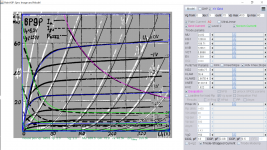
Here is update for Chinese 6P9P model, tested running on MicrCap:
Code:
**** 6P9P_CH ******************************************
* Created on 12/17/2020 17:06 using paint_kip.jar
* [url=http://www.dmitrynizh.com/tubeparams_image.htm]Model Paint Tools: Trace Tube Parameters over Plate Curves, Interactively[/url]
* Plate Curves image file: 6p9p_ch.png
* Data source link: <plate curves URL>
*----------------------------------------------------------------------------------
.SUBCKT 6P9P_CH P G2 G K ; LTSpice tetrode.asy pinout
* .SUBCKT 6P9P_CH P G K G2 ; Koren Pentode Pspice pinout
+ PARAMS: MU=24.82 KG1=1200.8 KP=109.71 KVB=1266.1 VCT=0.8866 EX=1.581 KG2=1089.77 KNEE=9120.18 KVC=1.922
+ KLAM=2E-9 KLAMG=2.667E-4  KD=2.961E-7 KC=0.1907 KR1=5.928E-4 KR2=0.00104 KVBG=0.002261 KB1=4.134 KB2=4.134 KB3=2.2 KB4=0.2218 KVBGI=0.00995 KNK=-1.734 KNG=0.2821
+ CCG=13P CGP=0.08P CCP=9.5P VGOFF=-0.9 IGA=1.4E-4 IGB=0.069 IGC=13.2 IGEX=1.32
* Vp_MAX=400 Ip_MAX=80 Vg_step=3 Vg_start=0 Vg_count=15
* X_MIN=107 Y_MIN=44 X_SIZE=706 Y_SIZE=564 FSZ_X=1296 FSZ_Y=736 XYGrid=false
* Rp=1400 Vg_ac=20 P_max=9 Vg_qui=-21 Vp_qui=300
* showLoadLine=n showIp=y isDHP=n isPP=n isAsymPP=n isUL=n showDissipLimit=y
* showIg1=y isInputSnapped=y addLocalNFB=n
* XYProjections=n harmonicPlot=y dissipPlot=n
* UL=0.43 EG2=150 gridLevel2=y addKink=n isTanhKnee=n advSigmoid=y
*----------------------------------------------------------------------------------
RE1  7 0  1G    ; DUMMY SO NODE 7 HAS 2 CONNECTIONS
E1   7 0  VALUE=  ; E1 BREAKS UP LONG EQUATION FOR G1.
+{V(G2,K)/KP*LOG(1+EXP((1/MU+(VCT+V(G,K))/SQRT(KVB+V(G2,K)*V(G2,K)))*KP))}
RE2  6 0  1G    ; DUMMY SO NODE 6 HAS 2 CONNECTIONS
E2  6 0  VALUE={(PWR(V(7),EX)+PWRS(V(7),EX))} ; Kg1 times KIT current
E4   8 0  VALUE={V(P,K)/KNEE/(KVBGI+V(6)*KVBG)}
E5  81 0  VALUE={PWR(V(8),KB1)}
E6  82 0  VALUE={PWR(V(8),KB2)}
E7  83 0  VALUE={PWR(V(8),KB3)}
E8   9 0  VALUE={PWR(1-EXP(-V(81)*(KC+KR1*V(82))/(KD+KR2*V(83))),KB4)*1.5708}
RE4  8 0  1
RE5 81 0  1
RE6 82 0  1
RE7 83 0  1
RE8  9 0  1
G1   P K  VALUE={V(6)/KG1*V(9)*(1+KLAMG*V(P,K))+KLAM*V(P,K)}
G2   G2 K  VALUE={V(6)/KG2*(KVC-V(9))/(1+KLAMG*V(P,K))}
RCP  P K  1G     ; FOR CONVERGENCE
C1   K G  {CCG}  ; CATHODE-GRID 1
C2   G P  {CGP}  ; GRID 1-PLATE
C3   K P  {CCP}  ; CATHODE-PLATE
RE23 G 0 1G
GG G K VALUE={(IGA+IGB/(IGC+V(P,K)))*(MU/KG1)*
+(PWR(V(G,K)-VGOFF,IGEX)+PWRS(V(G,K)-VGOFF,IGEX))}
.ENDS
Attachments
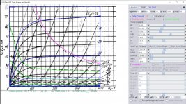
This is update for Russian 6Π9 model:
Code:
**** 6P9 ******************************************
* Created on 12/17/2020 18:43 using paint_kip.jar
* [url=http://www.dmitrynizh.com/tubeparams_image.htm]Model Paint Tools: Trace Tube Parameters over Plate Curves, Interactively[/url]
* Plate Curves image file: 6p9.png
* Data source link: <plate curves URL>
*----------------------------------------------------------------------------------
.SUBCKT 6P9 P G2 G K ; LTSpice tetrode.asy pinout
* .SUBCKT 6P9 P G K G2 ; Koren Pentode Pspice pinout
+ PARAMS: MU=26.56 KG1=898.44 KP=83.38 KVB=3772.98 VCT=0.993 EX=1.613 KG2=1259.34 KNEE=39.9 KVC=1.937
+ KLAM=2E-9 KLAMG=2.084E-7 KNEE2=40.07 KNEX=105.6  KNK=-0.5161 KNG=0.2257
+ CCG=13P CGP=0.06P CCP=7.5P VGOFF=-0.9 IGA=1.4E-4 IGB=0.069 IGC=13.2 IGEX=1.32
* Vp_MAX=400 Ip_MAX=80 Vg_step=3 Vg_start=6 Vg_count=15
* X_MIN=61 Y_MIN=14 X_SIZE=625 Y_SIZE=553 FSZ_X=1296 FSZ_Y=736 XYGrid=false
* Rp=1400 Vg_ac=20 P_max=9 Vg_qui=-15 Vp_qui=300
* showLoadLine=n showIp=y isDHP=n isPP=n isAsymPP=n isUL=n showDissipLimit=y
* showIg1=y isInputSnapped=y addLocalNFB=n
* XYProjections=n harmonicPlot=y dissipPlot=n
* UL=0.43 EG2=150 gridLevel2=y addKink=n isTanhKnee=y advSigmoid=n
*----------------------------------------------------------------------------------
RE1  7 0  1G    ; DUMMY SO NODE 7 HAS 2 CONNECTIONS
E1   7 0  VALUE=  ; E1 BREAKS UP LONG EQUATION FOR G1.
+{V(G2,K)/KP*LOG(1+EXP((1/MU+(VCT+V(G,K))/SQRT(KVB+V(G2,K)*V(G2,K)))*KP))}
RE2  6 0  1G    ; DUMMY SO NODE 6 HAS 2 CONNECTIONS
E2  6 0  VALUE={(PWR(V(7),EX)+PWRS(V(7),EX))} ; Kg1 times KIT current
G1   P K  VALUE={V(6)/KG1*ATAN((V(P,K)+KNEX)/KNEE)*TANH(V(P,K)/KNEE2)*(1+KLAMG*V(P,K))+KLAM*V(P,K)}
* Alexander Gurskii screen current, see audioXpress 2/2011
RE4K 4K K 1G ; Dummy, per Alex request
E4K 4K  4 VALUE={0} ; Dummy, per Alex request
G4K 4K K VALUE={V(6)/KG2*(KVC-ATAN((V(P,K)+KNEX)/KNEE)*TANH(V(P,K)/KNEE2))/(1+KLAMG*V(P,K))}
RCP  P K  1G     ; FOR CONVERGENCE
C1   K G  {CCG}  ; CATHODE-GRID 1
C2   G P  {CGP}  ; GRID 1-PLATE
C3   K P  {CCP}  ; CATHODE-PLATE
RE23 G 0 1G
GG G K VALUE={(IGA+IGB/(IGC+V(P,K)))*(MU/KG1)*
+(PWR(V(G,K)-VGOFF,IGEX)+PWRS(V(G,K)-VGOFF,IGEX))}
.ENDS
Attachments
Ok
I will bite.Why are those particular tubes named spice ?Yes i could google but I felt everyone could have a good laugh at my expense.I came here to learn.I have a huge inventory and lack the knowledge.Ignorance bliss knowledge is wealth.
SPICE is an acronym for "Simulation Program with Integrated Circuit Emphasis." It was developed in the 1970s at the University of California at Berkeley and it is a tool for simulating electronic circuits. Its use is not limited to integrated circuits however and good models exist for vacuum tubes as well. Vacuum tube SPICE models are the focus of this topic, as the name suggests.
Yes, you could have Googled this and found the same information. Learning requires effort on your part so don't expect others to spoon feed you everything you want to know. Be prepared to put in some work yourself.
Here is update for 6AG7_GE, briefly tested ok in MicroCap.
Code:*** 6AG7_GE ****************************************** * Created on 12/17/2020 15:47 using paint_kip.jar * [url=http://www.dmitrynizh.com/tubeparams_image.htm]Model Paint Tools: Trace Tube Parameters over Plate Curves, Interactively[/url] * Plate Curves image file: 6ag7-GE.png * Data source link: <plate curves URL> *---------------------------------------------------------------------------------- .SUBCKT 6AG7_GE P G2 G K ; LTSpice tetrode.asy pinout * .SUBCKT 6AG7_GE P G K G2 ; Koren Pentode Pspice pinout + PARAMS: MU=25.85 KG1=510.98 KP=148.26 KVB=5167.75 VCT=0.572 EX=1.296 KG2=360.85 KNEE=16582.14 KVC=1.884 + KLAM=2E-9 KLAMG=6.874E-5 KD=0.03952 KC=0.4435 KR1=4.56E-4 KR2=0.00104 KVBG=3.267E-4 KB1=3.564 KB2=3.474 KB3=2 KB4=0.264 KVBGI=0.001536 KNK=-0.8761 KNG=0.2739 KNPL=7.016 KNSL=75.98 KNPR=64.46 KNSR=100.61 + CCG=13P CGP=1.4P CCP=1.9P VGOFF=-0.9 IGA=1.4E-4 IGB=0.069 IGC=13.2 IGEX=1.32 * Vp_MAX=500 Ip_MAX=200 Vg_step=2 Vg_start=8 Vg_count=15 * X_MIN=36 Y_MIN=28 X_SIZE=727 Y_SIZE=592 FSZ_X=1296 FSZ_Y=736 XYGrid=false * Rp=1400 Vg_ac=20 P_max=9 Vg_qui=-6 Vp_qui=300 * showLoadLine=n showIp=y isDHP=n isPP=n isAsymPP=n isUL=n showDissipLimit=y * showIg1=y isInputSnapped=y addLocalNFB=n * XYProjections=n harmonicPlot=y dissipPlot=n * UL=0.43 EG2=150 gridLevel2=y addKink=y isTanhKnee=n advSigmoid=y *---------------------------------------------------------------------------------- RE1 7 0 1G ; DUMMY SO NODE 7 HAS 2 CONNECTIONS E1 7 0 VALUE= ; E1 BREAKS UP LONG EQUATION FOR G1. +{V(G2,K)/KP*LOG(1+EXP((1/MU+(VCT+V(G,K))/SQRT(KVB+V(G2,K)*V(G2,K)))*KP))} RE2 6 0 1G ; DUMMY SO NODE 6 HAS 2 CONNECTIONS E2 6 0 VALUE={(PWR(V(7),EX)+PWRS(V(7),EX))} ; Kg1 times KIT current E4 8 0 VALUE={V(P,K)/KNEE/(KVBGI+V(6)*KVBG)} E5 81 0 VALUE={PWR(V(8),KB1)} E6 82 0 VALUE={PWR(V(8),KB2)} E7 83 0 VALUE={PWR(V(8),KB3)} E8 9 0 VALUE={PWR(1-EXP(-V(81)*(KC+KR1*V(82))/(KD+KR2*V(83))),KB4)*1.5708} RE4 8 0 1 RE5 81 0 1 RE6 82 0 1 RE7 83 0 1 RE8 9 0 1 RE21 21 0 1 E21 21 0 VALUE={V(6)/KG1*V(9)} ; Ip with knee but no slope and no kink RE22 22 0 1 ; E22: kink curr deviation for plate E22 22 0 VALUE={V(21)*LIMIT(KNK-V(G,K)*KNG,0,0.3)*(-ATAN((V(P,K)-KNPL)/KNSL)+ATAN((V(P,K)-KNPR)/KNSR))} G1 P K VALUE={V(21)*(1+KLAMG*V(P,K))+KLAM*V(P,K) + V(22)} G2 G2 K VALUE={V(6)/KG2*(KVC-V(9))/(1+KLAMG*V(P,K)) - V(22)} RCP P K 1G ; FOR CONVERGENCE C1 K G {CCG} ; CATHODE-GRID 1 C2 G P {CGP} ; GRID 1-PLATE C3 K P {CCP} ; CATHODE-PLATE RE23 G 0 1G GG G K VALUE={(IGA+IGB/(IGC+V(P,K)))*(MU/KG1)* +(PWR(V(G,K)-VGOFF,IGEX)+PWRS(V(G,K)-VGOFF,IGEX))} .ENDS
Unfortunately it still gives me errors (Part and node have the same name X1 G2)
Unfortunately it still gives me errors (Part and node have the same name X1 G2)
Yes, that is a only warning, it will continue to sim. Some are real errors like "Matrix is singular", I can't solve it, and it also appears in LTspice. These models using "Advance Knee" options is a little too much for Spice program to handle as explained in the errors messages of MicroCap.
Yes, that is a only warning, it will continue to sim. Some are real errors like "Matrix is singular", I can't solve it, and it also appears in LTspice. These models using "Advance Knee" options is a little too much for Spice program to handle as explained in the errors messages of MicroCap.
- Home
- Amplifiers
- Tubes / Valves
- Vacuum Tube SPICE Models