Thank you Ray for your efforts!
@ Baldin,
I tried to get your error messages, but failed. I included my 6111_i2 model in both ways, like you did it and also like Ray did - both times no errors...
I recommend to overtake Ray's .asc file, as your .asc file seems to be damaged somehow (we can't open it). After adapting the .inc path to were your 6111_i2 model file is stored, it should hopefully run.
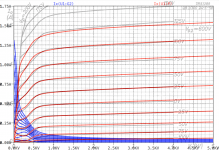
PS: It seems that your SRPP stage suffers a bit under U2 grid current (up to 44uA), but, depending on the used 6111 sample, it may be ok in practice.
How ever, if Vcc is increased to 150V, the U2 grid current is reduced to sub uA range.
all the best, Adrian
@ Baldin,
I tried to get your error messages, but failed. I included my 6111_i2 model in both ways, like you did it and also like Ray did - both times no errors...
I recommend to overtake Ray's .asc file, as your .asc file seems to be damaged somehow (we can't open it). After adapting the .inc path to were your 6111_i2 model file is stored, it should hopefully run.
PS: It seems that your SRPP stage suffers a bit under U2 grid current (up to 44uA), but, depending on the used 6111 sample, it may be ok in practice.
How ever, if Vcc is increased to 150V, the U2 grid current is reduced to sub uA range.
all the best, Adrian
Thanks Adrian and Ray, for all you effort. Maybe it has something to do with me just changing for LTSpice XVII ....
Anyway will use the file from Ray.
About the SRPP stage; thanks for suggestions ... sure need to look more into this. What I'm needing is a stage with a gain of ca -3x, and producing predominantly H2 distortion at ca 1.1 Vpp in. To be used as the input stage of a class d amp
.... and I have zero experience with tubes
... will also have to find a good supplier of non-fake tubes in eu ... suggestions?
Thanks and kind regards Baldin
Hello.
There is someone so good to create a tube model qb3 / 300. For me there is no problem modeling triodes but pentodes are a big problem.
Thank you.
Piotr
Hi Piotr
This Tube was the hardest job ever, but now I'm satisfied with the result!
kind regards, Adrian
Code:
*QB3/300 LTspice model based on the generic tetrode/pentode model from Adrian Immler, version i4, Mar. 2020
*A version log is at the end of this file
*Params fitted to Philips datasheet by Adrian Immler, Mar. 2020
*This model is an enhancement of Adrians generic triode model to achieve tetrode/pentode behaviour.
*Hence, it is also suitable when the tetrode/pentode is "triode connected".
*Convenient for tetrodes, power beam tetrodes and g3-grounded pentodes.
*Copes secondary emission effect!
*               PH=Philips
*               | version i4
*               | |  plate (in this model, "anode" means the internal virtual triode anode)
*               | |  | grid2
*               | |  | |  grid1
*               | |  | |  |  cathode
*               | |  | |  |  |
.subckt QB3/300.PHi4 P G2 G1 K
.params
*Parameters for the space charge current @ Vg <= 0
+ mu1 = 5.6      ;Main factor for voltage gain @ constant Ia in triode mode
+ ks = 1k86      ;Permeance factor. Has to be readjusted if xs is changed
+ Vg0 = 5        ;Offsets the Ia-traces on the Va axis. Electrode material's contact potential
+ kp = 50        ;Mimics the island effect
+ xs = 1.45      ;Determines the curve of the Ia traces. Typically between 1.2 and 1.8
*
*Parameters for an optional space charge current reduction @ Vg > 0
+ kIsr = 0       ;Va independable Is reduction, a function of Vg1
+ Rg1i = 1       ;Internal grid1 resistor which causes an extra Is drop when Va approaches zero.
*
*Parameters for assigning the space charge current to Ia and Ig @ Vg > 0 and small Va
+ kB1 = 0.1      ;Describes how fast Ia_virtual drops to zero when Va_virtual approaches zero.
+ radl = 210     ;Differential resistance for the Ia emission limit @ very small Va and Vg > 0
+ tsh = 12       ;Ia transmission sharpness from 1th to 2nd Ia area. Keep between 3 and 20. Start with 20.
+ xl = 1.2       ;Exponent for the emission limit
+ Vctl = 0 f=0   ;Offsets the Ia emission limit trace on the Va axis. f=related Vg1 koeff.
*
*Parameters of the grid-cathode vacuum diode
+ kg1 = 2k1      ;Inverse scaling factor for the Va independent part of Ig (caution - interacts with xg!)
+ Vctg1 = 25     ;Offsets the log Ig-traces on the Vg axis. Electrode material's contact potential
+ xg1 = 1        ;Determines the curve of the Ig slope versus (positive) Vg and Va >> 0
+ VT = 0.1       ;Log(Ig) slope @ Vg<0. VT=k/q*Tk (cathodes absolute temp, typically 1150K)
*
*Parameters for the caps
+ cg1p  = 0p05   ;according datasheet
+ cg1All= 10p8   ;according datasheet
+ CpAll = 3p5    ;according datasheet
+ Cpk  = 0p01    ;not mentioned in datasheet
*
*Parameters to enhance the triode model to a pentode model
+ mu2 = 85       ;1/mu2 is the fraction of Vp which together with Vg2i builds the virtual Triode-Anode Voltage
+ kB2 = 0.02     ;Describes how fast Ip drops to zero when Vp approaches zero.
+ Rg2i = 80      ;Internal grid2 resistor. Causes an Is reduction when Ig2 increases while Vp drops
+ fr2 = 0.015    ;determines the residual ig2 fraction @ high Va values
+ ftfr2 = 0      ;if fr2 showes a Vg2 dependancy, this can be considered with this parameter
*
*Parameters to mimic the secondary emission (inspired from Derk Reefmans approach)
+ co = 1.5       ;decribes the crossover region (Ise drop when Va increase). between 0 and 9
+ Vse=265   a=0.1;Va where the sec. emission is strongest. a=related Vg1 coefficient
+ Ise0=110m b=0m1;sec. emission peak current @ Vg=0. b=related Vg1 coefficient
+ Vg2ref = 600   ;Vg2 where the following coeffficients has no influence to the emission effect:
+ c = -3m6       ;Vg2 coefficient of a
+ d = 5m         ;exp Vg2 coefficient of Ise0
+ e = 0          ;Vg2 coeff. of b
*
*Calculated parameters
+ kl = pow(1/(radl*xl*Ild**(1-1/xl)),-xl) ;Reduces the xl influence to the Ia slope @ small Va
+ Ild = sqrt(radl)*1m ;Current where the limited anode a.c. resistance is set according to radl.
*
*Space charge current model
Bggi GG1i 0 V=v(G1i,K)+Vg0 - v(G1,K)*(1-1/(1+kIsr*max(0,v(G1,K)))) ;Effective internal grid voltage.
Bahc Ahc 0 V=uramp(v(P,K)/mu2+v(G2i,K)) ;voltage of the virtual triode anode, hard cut to zero
Bst St 0 V=max(v(GG1i)+v(Ahc)/(mu1), v(Ahc)/kp*ln(1+exp(kp*(1/mu1+v(GG1i)/(1+v(Ahc))))));Steering volt.
Bs Ai K I=1/ks*pow(v(St),xs) ;Langmuir-Childs law for the space charge current Is
*
*Anode current limit @ small Va
.func smin(x,y,n) {pow(pow(x + 1f, -n)+pow(y+1f, -n), -1/n)} ;Min-function with smooth trans.
Ra A Ai 1
Bpl G2i P I=i(Rp) - smin(1/kl*pow(v(P,K)+min(0,Vctl+f*v(G1,K)),xl),i(Rp),tsh);Ip emission limit
*
*Grid model
Rg1i G1 G1i {Rg1i} ;Internal grid resistor for "Ia-reduction" @ Vg > 0
.func Ivd(Vvd, kvd, xvd, VTvd)  {if(Vvd < 3, 1/kvd*pow(VTvd*xvd*ln(1+exp(Vvd/VTvd/xvd)),xvd), 1/kvd*pow(Vvd, xvd))}
;.func Ivd(Vvd, kvd, xvd, VTvd) {1/kvd*pow(VTvd*xvd*ln(1+exp(Vvd/VTvd/xvd)),xvd)} ;Vacuum diode function
Bg1vd G1 K I=Ivd(v(G1,K)+Vctg1-1m*sqrt(v(Ahc)), kg1, xg1, VT) ;Grid-cathode vacuum diode
Bg1r G1i Ai I=ivd(v(GG1i),ks, xs, 0.8*VT)/(1+kB1*v(Ahc));Is reflection to grid when Va appr. zero
Bs0 Ai K I=ivd(v(GG1i),ks, xs, 0.8*VT) - 1/ks*pow(v(GG1i),xs) ;Compensates neg Ia
*@ small Va and Vg near zero
*
*additional model parts necessary for a pentode
Rg2i G2 G2i {Rg2i}
Rp P A 1
Bg2r G2i A I=i(Ra)*((1-frg2())/(1+kB2*max(0,v(P,K))) ) ; Va dependable ig2 part, reflected from the plate
Bg2f G2  A I=i(Ra)*frg2() ; Va independable ig2 part. Not to lead this current over Rg2i improves convergence
.func frg2() {fr2*exp(ftfr2*(v(G2,K)-600))}
*
*model for secondary emission effect
*nomalizing function nf(sh) ensures that the peak of y=x*(1-tanh(sh(x-1)) is always at x=1 while sh=0..9
.func nf(z) {609m/z + 293m + 107m*z - 5.71m*z*z}
.func sh() {pow(co,2)} ;results in a more linear control of the cross over region with the param co
Bsee G2 P I=min(Ise()*nf(sh())*xf()*(1-tanh(sh()*(nf(sh())*xf()-1))) / (nf(sh())*(1-tanh(sh()*(nf(sh())-1)))),i(Rp)-i(Bpl))
.func Ise() {smin(uramp(Isef() - bf()*v(G1,K)),0.98*i(Rp),2)} ;avoides neg. Iplate caused by strong sec. em.
.func xf() {v(P,K)/(1m+uramp(Vse-af()*v(G1,K)))}; moves the sec emission peak to the wanted voltage Vsep
.func af() {a + c*(v(G2,K)-Vg2ref)}
.func Isef()   {Ise0 * exp(d*(v(G2,K)-Vg2ref))}
.func bf()  {b + e*((v(G2,K)-Vg2ref))}
*
*Caps
C1 G1 P {cg1p}
C2 G1 K {(cg1All-cg1p)/2} ;As this model does not consider the ambient as further electrodes for parasitic caps,
;best way is to assume this " g1 to all" cap as it would be half to cathode and half to g2 (after substraction of cg1p).
C3 G1 G2 {(cg1All-cg1p)/2}
C4 P K {cpk}
C5 P G2 {cpAll-cpk-cg1p}
.end
*
*Version log
*i1 :Initial version
*i2 :Pin order changed to the more common order "P G2 G1 K" (Thanks to Markus Gyger for his tip)
*i3 :residual ig2 @ large Va introduced; 2nd emission effect introduced;
;Va indep. grid current parts no longer lead over internal grid resistors for better convergence
*i4 :to improve convegence, the Ia reduction @ pos Vg is no longer done by Rg1i. Instead, kIsr introduced
;Furthermore, ks and Vg0 are set directly, as rad and Vct turned out to be usefull for triodes only
*i4f :Major bug fixed. Tube works now also when Cathode not grounded (for cathode follower and the like)
Attachments
Thanks Adrian and Ray, for all you effort. Maybe it has something to do with me just changing for LTSpice XVII ....
Anyway will use the file from Ray.
About the SRPP stage; thanks for suggestions ... sure need to look more into this. What I'm needing is a stage with a gain of ca -3x, and producing predominantly H2 distortion at ca 1.1 Vpp in. To be used as the input stage of a class d amp
.... and I have zero experience with tubes
... will also have to find a good supplier of non-fake tubes in eu ... suggestions?
Thanks and kind regards Baldin
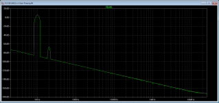
It looks like you want an inverting amp. So here is one using the E88CC (or ECC88 or 6922) that provides a gain of x3, inverting, with low THD, mostly second harmonic (see attached FFT plot). The E88CC SPICE model I used is also attached; as before, I store these in a "User" folder so you will need to modify the path to this file on your own computer.
This particular tube is very linear and works well at relatively low plate voltages. I've used 200 volts for the plate supply instead of the 100 volts you used in your schematic but hopefully you have some flexibility here.
Will this work?
Attachments
Thank you! QB3-300 is the same as 4-125 I requested ! Thank you so much!Hi Piotr
This Tube was the hardest job ever, but now I'm satisfied with the result!
kind regards, Adrian
Code:*QB3/300 LTspice model based on the generic tetrode/pentode model from Adrian Immler, version i4, Mar. 2020 *A version log is at the end of this file *Params fitted to Philips datasheet by Adrian Immler, Mar. 2020 *This model is an enhancement of Adrians generic triode model to achieve tetrode/pentode behaviour. *Hence, it is also suitable when the tetrode/pentode is "triode connected". *Convenient for tetrodes, power beam tetrodes and g3-grounded pentodes. *Copes secondary emission effect! * PH=Philips * | version i4 * | | plate (in this model, "anode" means the internal virtual triode anode) * | | | grid2 * | | | | grid1 * | | | | | cathode * | | | | | | .subckt QB3/300.PHi4 P G2 G1 K .params *Parameters for the space charge current @ Vg <= 0 + mu1 = 5.6 ;Main factor for voltage gain @ constant Ia in triode mode + ks = 1k86 ;Permeance factor. Has to be readjusted if xs is changed + Vg0 = 5 ;Offsets the Ia-traces on the Va axis. Electrode material's contact potential + kp = 50 ;Mimics the island effect + xs = 1.45 ;Determines the curve of the Ia traces. Typically between 1.2 and 1.8 * *Parameters for an optional space charge current reduction @ Vg > 0 + kIsr = 0 ;Va independable Is reduction, a function of Vg1 + Rg1i = 1 ;Internal grid1 resistor which causes an extra Is drop when Va approaches zero. * *Parameters for assigning the space charge current to Ia and Ig @ Vg > 0 and small Va + kB1 = 0.1 ;Describes how fast Ia_virtual drops to zero when Va_virtual approaches zero. + radl = 210 ;Differential resistance for the Ia emission limit @ very small Va and Vg > 0 + tsh = 12 ;Ia transmission sharpness from 1th to 2nd Ia area. Keep between 3 and 20. Start with 20. + xl = 1.2 ;Exponent for the emission limit + Vctl = 0 f=0 ;Offsets the Ia emission limit trace on the Va axis. f=related Vg1 koeff. * *Parameters of the grid-cathode vacuum diode + kg1 = 2k1 ;Inverse scaling factor for the Va independent part of Ig (caution - interacts with xg!) + Vctg1 = 25 ;Offsets the log Ig-traces on the Vg axis. Electrode material's contact potential + xg1 = 1 ;Determines the curve of the Ig slope versus (positive) Vg and Va >> 0 + VT = 0.1 ;Log(Ig) slope @ Vg<0. VT=k/q*Tk (cathodes absolute temp, typically 1150K) * *Parameters for the caps + cg1p = 0p05 ;according datasheet + cg1All= 10p8 ;according datasheet + CpAll = 3p5 ;according datasheet + Cpk = 0p01 ;not mentioned in datasheet * *Parameters to enhance the triode model to a pentode model + mu2 = 85 ;1/mu2 is the fraction of Vp which together with Vg2i builds the virtual Triode-Anode Voltage + kB2 = 0.02 ;Describes how fast Ip drops to zero when Vp approaches zero. + Rg2i = 80 ;Internal grid2 resistor. Causes an Is reduction when Ig2 increases while Vp drops + fr2 = 0.015 ;determines the residual ig2 fraction @ high Va values + ftfr2 = 0 ;if fr2 showes a Vg2 dependancy, this can be considered with this parameter * *Parameters to mimic the secondary emission (inspired from Derk Reefmans approach) + co = 1.5 ;decribes the crossover region (Ise drop when Va increase). between 0 and 9 + Vse=265 a=0.1;Va where the sec. emission is strongest. a=related Vg1 coefficient + Ise0=110m b=0m1;sec. emission peak current @ Vg=0. b=related Vg1 coefficient + Vg2ref = 600 ;Vg2 where the following coeffficients has no influence to the emission effect: + c = -3m6 ;Vg2 coefficient of a + d = 5m ;exp Vg2 coefficient of Ise0 + e = 0 ;Vg2 coeff. of b * *Calculated parameters + kl = pow(1/(radl*xl*Ild**(1-1/xl)),-xl) ;Reduces the xl influence to the Ia slope @ small Va + Ild = sqrt(radl)*1m ;Current where the limited anode a.c. resistance is set according to radl. * *Space charge current model Bggi GG1i 0 V=v(G1i,K)+Vg0 - v(G1,K)*(1-1/(1+kIsr*max(0,v(G1,K)))) ;Effective internal grid voltage. Bahc Ahc 0 V=uramp(v(P,K)/mu2+v(G2i,K)) ;voltage of the virtual triode anode, hard cut to zero Bst St 0 V=max(v(GG1i)+v(Ahc)/(mu1), v(Ahc)/kp*ln(1+exp(kp*(1/mu1+v(GG1i)/(1+v(Ahc))))));Steering volt. Bs Ai K I=1/ks*pow(v(St),xs) ;Langmuir-Childs law for the space charge current Is * *Anode current limit @ small Va .func smin(x,y,n) {pow(pow(x + 1f, -n)+pow(y+1f, -n), -1/n)} ;Min-function with smooth trans. Ra A Ai 1 Bpl G2i P I=i(Rp) - smin(1/kl*pow(v(P,K)+min(0,Vctl+f*v(G1,K)),xl),i(Rp),tsh);Ip emission limit * *Grid model Rg1i G1 G1i {Rg1i} ;Internal grid resistor for "Ia-reduction" @ Vg > 0 .func Ivd(Vvd, kvd, xvd, VTvd) {if(Vvd < 3, 1/kvd*pow(VTvd*xvd*ln(1+exp(Vvd/VTvd/xvd)),xvd), 1/kvd*pow(Vvd, xvd))} ;.func Ivd(Vvd, kvd, xvd, VTvd) {1/kvd*pow(VTvd*xvd*ln(1+exp(Vvd/VTvd/xvd)),xvd)} ;Vacuum diode function Bg1vd G1 K I=Ivd(v(G1,K)+Vctg1-1m*sqrt(v(Ahc)), kg1, xg1, VT) ;Grid-cathode vacuum diode Bg1r G1i Ai I=ivd(v(GG1i),ks, xs, 0.8*VT)/(1+kB1*v(Ahc));Is reflection to grid when Va appr. zero Bs0 Ai K I=ivd(v(GG1i),ks, xs, 0.8*VT) - 1/ks*pow(v(GG1i),xs) ;Compensates neg Ia *@ small Va and Vg near zero * *additional model parts necessary for a pentode Rg2i G2 G2i {Rg2i} Rp P A 1 Bg2r G2i A I=i(Ra)*((1-frg2())/(1+kB2*max(0,v(P,K))) ) ; Va dependable ig2 part, reflected from the plate Bg2f G2 A I=i(Ra)*frg2() ; Va independable ig2 part. Not to lead this current over Rg2i improves convergence .func frg2() {fr2*exp(ftfr2*(v(G2,K)-600))} * *model for secondary emission effect *nomalizing function nf(sh) ensures that the peak of y=x*(1-tanh(sh(x-1)) is always at x=1 while sh=0..9 .func nf(z) {609m/z + 293m + 107m*z - 5.71m*z*z} .func sh() {pow(co,2)} ;results in a more linear control of the cross over region with the param co Bsee G2 P I=min(Ise()*nf(sh())*xf()*(1-tanh(sh()*(nf(sh())*xf()-1))) / (nf(sh())*(1-tanh(sh()*(nf(sh())-1)))),i(Rp)-i(Bpl)) .func Ise() {smin(uramp(Isef() - bf()*v(G1,K)),0.98*i(Rp),2)} ;avoides neg. Iplate caused by strong sec. em. .func xf() {v(P,K)/(1m+uramp(Vse-af()*v(G1,K)))}; moves the sec emission peak to the wanted voltage Vsep .func af() {a + c*(v(G2,K)-Vg2ref)} .func Isef() {Ise0 * exp(d*(v(G2,K)-Vg2ref))} .func bf() {b + e*((v(G2,K)-Vg2ref))} * *Caps C1 G1 P {cg1p} C2 G1 K {(cg1All-cg1p)/2} ;As this model does not consider the ambient as further electrodes for parasitic caps, ;best way is to assume this " g1 to all" cap as it would be half to cathode and half to g2 (after substraction of cg1p). C3 G1 G2 {(cg1All-cg1p)/2} C4 P K {cpk} C5 P G2 {cpAll-cpk-cg1p} .end * *Version log *i1 :Initial version *i2 :Pin order changed to the more common order "P G2 G1 K" (Thanks to Markus Gyger for his tip) *i3 :residual ig2 @ large Va introduced; 2nd emission effect introduced; ;Va indep. grid current parts no longer lead over internal grid resistors for better convergence *i4 :to improve convegence, the Ia reduction @ pos Vg is no longer done by Rg1i. Instead, kIsr introduced ;Furthermore, ks and Vg0 are set directly, as rad and Vct turned out to be usefull for triodes only *i4f :Major bug fixed. Tube works now also when Cathode not grounded (for cathode follower and the like)
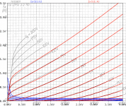
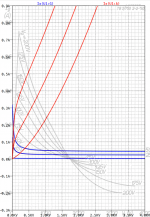
Since we are at big bottles now can you check TB3-750 triode?
Hi panos29
I reale didn't know that a QB3-300 is the same as a 4-125
Here your TB3-750 model.
Please be aware that this model is valid up to Vg=50V. For higher grid voltages, it delivers wrong grid currents.
I reale didn't know that a QB3-300 is the same as a 4-125 Here your TB3-750 model.
Please be aware that this model is valid up to Vg=50V. For higher grid voltages, it delivers wrong grid currents.
Code:
*TB3-750 LTspice model based on the generic triode model from Adrian Immler, version i4
*A version log is at the end of this file
*Params fitted to the Philips data sheet by Adrian Immler, Mar. 2020
*The high fit quality is presented at adrianimmler.simplesite.com
*The potential of the negative heater pin is refered as "0V" for the graphs.
*History's best of tube decribing art (plus some new ideas) is merged to this new approach.
*@ neg. Vg, Ia accuracy is similar to Koren or Ayumi models.
*@ small neg. Vg, the "Anlauf" current is considered.
*@ pos. Vg, Ig and Ia accuracy is on a unrivaled level.
*This offers new simulation possibilities like bias point setting with MOhm grid resistor,
*Audion radio circuits, low voltage amps, guitar distortion stages or pulsed stages.
* Philips
* | version i4
* | | anode (plate)
* | | | grid
* | | | | cathode
* | | | | |
.subckt TB3-750.PHi4 A G K
.params
*Parameters for the space charge current @ Vg <= 0
+ mu = 27 ;Determines the voltage gain @ constant Ia
+ rad = 8k2 ;Differential anode resistance, set @ Iad and Vg=0V
+ Vct = 3 ;Offsets the Ia-traces on the Va axis. Electrode material's contact potential
+ kp = 140 ;Mimics the island effect
+ xs = 1.5 ;Determines the curve of the Ia traces. Typically between 1.2 and 1.8
*
*Parameters for assigning the space charge current to Ia and Ig @ Vg > 0
+ kB = 0.04 ;Describes how fast Ia drops to zero when Va approaches zero.
+ radl = 220 ;Differential resistance for the Ia emission limit @ very small Va and Vg > 0
+ tsh = 12 ;Ia transmission sharpness from 1th to 2nd Ia area. Keep between 3 and 20. Start with 20.
+ xl = 1.2 ;Exponent for the emission limit
*
*Parameters of the grid-cathode vacuum diode
+ kvdg = 75 ;virtual vacuumdiode. Causes an Ia reduction @ Ig > 0.
+ kg = 1k3 ;Inverse scaling factor for the Va independent part of Ig (caution - interacts with xg!)
+ Vctg = 5 ;Offsets the log Ig-traces on the Vg axis. Electrode material's contact potential
+ xg = 1.0 ;Determines the curve of the Ig slope versus (positive) Vg and Va >> 0
+ VT = 0.1 ;Log(Ig) slope @ Vg<0. VT=k/q*Tk (cathodes absolute temp, typically 1150K)
+ Vft2 = 0 gft2 = 0 ;finetunes the gridcurrent @ low Va and Vg near zero
*
*Parameters for the caps
+ cag = 5p3 ;From datasheet
+ cak = 0p15 ;From datasheet
+ cgk = 7p ;From datasheet
*
*special purpose parameters
+ os = 1 ;Overall scaling factor, if a user wishes to simulate manufacturing tolerances
*
*Calculated parameters
+ Iad = 100/rad ;Ia where the anode a.c. resistance is set according to rad.
+ ks = pow(mu/(rad*xs*Iad**(1-1/xs)),-xs) ;Reduces the unwished xs influence to the Ia slope
+ ksnom = pow(mu/(rad*1.5*Iad**(1-1/1.5)),-1.5) ;Sub-equation for calculating Vg0
+ Vg0 = Vct + (Iad*ks)**(1/xs) - (Iad*ksnom)**(2/3) ;Reduces the xs influence to Vct.
+ kl = pow(1/(radl*xl*Ild**(1-1/xl)),-xl) ;Reduces the xl influence to the Ia slope @ small Va
+ Ild = sqrt(radl)*1m ;Current where the Il a.c. resistance is set according to radl.
*
*Space charge current model
Bggi GGi 0 V=v(Gi,K)+Vg0 ;Effective internal grid voltage.
Bahc Ahc 0 V=uramp(v(A,K)) ;Anode voltage, hard cut to zero @ neg. value
Bst St 0 V=uramp(max(v(GGi)+v(A,K)/(mu), v(A,K)/kp*ln(1+exp(kp*(1/mu+v(GGi)/(1+v(Ahc)))))));Steering volt.
Bs Ai K I=os/ks*pow(v(St),xs) ;Langmuir-Childs law for the space charge current Is
*
*Anode current limit @ small Va
.func smin(z,y,k) {pow(pow(z+1f, -k)+pow(y+1f, -k), -1/k)} ;Min-function with smooth trans.
Ra A Ai 1
Bgl Gi A I=min(i(Ra)-smin(1/kl*pow(v(Ahc),xl),i(Ra),tsh),i(Bgvd)*exp(4*v(G,K))) ;Ia emission limit
*
*Grid model
Bvdg G Gi I=1/kvdg*pwrs(v(G,Gi),1.5) ;Reduces the internal effective grid voltage when Ig rises
Rgip G Gi 1G ;avoids some warnings
.func Ivd(Vvd, kvd, xvd, VTvd) {if(Vvd < 3, 1/kvd*pow(VTvd*xvd*ln(1+exp(Vvd/VTvd/xvd)),xvd), 1/kvd*pow(Vvd, xvd))} ;Vacuum diode function
Bgvd Gi K I=Ivd(v(G,K) + Vctg - uramp(-v(A,K)/mu), kg/os, xg, VT)
.func ft2() {gft2*(1-tanh(3*(v(G,K)+Vft2)))} ;Finetuning-func. improves ig-fit @ Vg near -0.5V, low Va.
Bgr Gi Ai I=ivd(v(GGi),ks/os, xs, 0.8*VT)/(1+ft2()+kB*v(Ahc));Is reflection to grid when Va approaches zero
Bs0 Ai K I=ivd(v(GGi),ks/os, xs, 0.8*VT)/(1+ft2()) - os/ks*pow(v(GGi),xs) ;Compensates neg Ia @ small Va and Vg near zero
*
*Caps
C1 A G {cag}
C2 A K {cak}
C3 G K {cgk}
.end
*
*Version log
*i1 :Initial version
*i2 :Pin order changed to the more common order âA G Kâ (Thanks to Markus Gyger for his tip)
*i3 :bugfix of the Ivd-function: now also usable for larger Vvd
*i4: Rgi replaced by a virtual vacuum diode (better convergence). ft1 deleted (no longer needed)
;2 new prarams for Ig finetuning @ Va and Vg near zero. New emission skaling factor ke for aging etc.Attachments
Hi Adrian, it looks like you have done great work. Did you ever do a model for the 6SN7 triode. There are several models further back on this thread, but they are from some years ago. If you have, I would love to have it. Many thanks.Hi Piotr
This Tube was the hardest job ever, but now I'm satisfied with the result!
kind regards, Adrian
Has anyone else got a 6SN7 LTSpice model? If so, could he/she share it? Thanks.Hi Adrian, it looks like you have done great work. Did you ever do a model for the 6SN7 triode. There are several models further back on this thread, but they are from some years ago. If you have, I would love to have it. Many thanks.
Code:
*
* Generic triode model: 6SN7
* Copyright 2003--2008 by Ayumi Nakabayashi, All rights reserved.
* Version 3.10, Generated on Sat Mar  8 22:40:58 2008
*            Plate
*            | Grid
*            | | Cathode
*            | | |
.SUBCKT 6SN7 A G K
BGG   GG   0 V=V(G,K)+0.54900933
BM1   M1   0 V=(0.020494606*(URAMP(V(A,K))+1e-10))**-0.76277031
BM2   M2   0 V=(0.66290422*(URAMP(V(GG)+URAMP(V(A,K))/16.448024)+1e-10))**2.2627703
BP    P    0 V=0.0012465111*(URAMP(V(GG)+URAMP(V(A,K))/24.812067)+1e-10)**1.5
BIK   IK   0 V=U(V(GG))*V(P)+(1-U(V(GG)))*0.00074417047*V(M1)*V(M2)
BIG   IG   0 V=0.0003834058*URAMP(V(G,K))**1.5*(URAMP(V(G,K))/(URAMP(V(A,K))+URAMP(V(G,K)))*1.2+0.4)
BIAK  A    K I=URAMP(V(IK,IG)-URAMP(V(IK,IG)-(0.0006816103*URAMP(V(A,K))**1.5)))+1e-10*V(A,K)
BIGK  G    K I=V(IG)
* CAPS
CGA   G    A 4p
CGK   G    K 3p
CAK   A    K 1.2p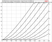
.ENDSQQE03/12 Spice model?
That looks great. Would it be possible for you to post that QQE03/12 Spice model?
I finally got the simulations done.
As a conclusion I would say that your QQE03/12 Spice model is quite accurate.
That looks great. Would it be possible for you to post that QQE03/12 Spice model?
Hello.
* E80CC LTSpice model 0.1ma
.subckt E80CC P G K
Bp P K I=(0.02515899492m)*uramp(V(P,K)*ln(1.0+(-0.1412885507)+exp((2.949808028)+(2.949808028)*((33.33832744)+(-961.1308157m)*V(G,K))*V(G,K)/sqrt((42.21997537)**2+(V(P,K)-(-4.808403134))**2)))/(2.949808028))**(1.251891153)
Cgk G K 3.0p
Cpk P K 2.6p
Cgp G P 3.5p
Rpk P K 1G
d3 G K dx1
.model dx1 d(is=1n rs=2k cjo=1pf N=1.5 tt=1n)
.ends E80CC
Piotr
Has anyone got a E80CC LTSpice model? If so, could he share it? Thanks.
* This library was developed by Norman Koren.
*
******************
.SUBCKT E80CC 1 2 3 ; P G C (Triode)
* Philips data sheet Dec 1968
* library format: LTSpice 31-May-2008
X1 1 2 3 TRIODE MU=32.74 EX=1.468 KG1=2447.9 KP=235.61 KVB=2119.4 VCT=0.50 RGI=2000 CCG=3.0p CGP=2.2p CCP=2.3p ;
.ENDS E80CC
******************
Has anyone got a E80CC LTSpice model? If so, could he share it? Thanks.
Code:
* ==============================================================
* E80CC LTSpice model
* Modified Koren model (8 parameters): mean fit error 0.114556mA
* Traced by Wayne Clay on 05/24/2018 using Engauge Digigtizer and
* Curve Captor v0.9.1 from Philips data sheet
* ==============================================================
.subckt E80CC  P G K
    Bp  P K  I=
+ (0.01823246698m)*uramp(V(P,K)*ln(1.0+(-0.1122041877)+exp((0.8506315156)+
+ (0.8506315156)*((52.69367678)+(-3800.239263m)*V(G,K))*V(G,K)/sqrt((46.38864305)**2+
+ (V(P,K)-(17.14739421))**2)))/(0.8506315156))**(1.240091528)
    Cgp G P 3.8p ; 0.7p added (3.1p)
    Cgk G K 3.1p ; 0.7p added (2.4p)
    Cpk P K 0.65p ; 0.2p added (0.45p)
    Rpk P K 1G ; to avoid floating nodes
    d3  G K dx1
.model dx1 d(is=1n rs=2k cjo=1pf N=1.5 tt=1n)
.ends E80CCAttachments
Is it not high time for one of the admins to put up a "sticky" entitled "How to make your own spice model" and include a link to Dmitri's painting software? It is very easy to simply cut and paste a picture of some curves and then alter the parameters for Kb, Ex, Kg1 etc to match the imported picture. You then simply read off the capacitances from the datasheet and add the filament current if DHT and you're done.
Here's one I did earlier.

kind regards
Marek
Here's one I did earlier.
kind regards
Marek
- Home
- Amplifiers
- Tubes / Valves
- Vacuum Tube SPICE Models