Pillo69: Micro-Cap is a really nice piece of freeware, but people in DIYA have been using LTspice for a long time, so I suggest you start with that, for its better support, i.e. Mooly's tutorial.
Hi Adrian,
Sorry disturb you but I try as an exercise to model this tube EL33, can you please check when you can no hurry this model, because I do not know if is right or not, I know you are very prepared in this matter....all the best
Hi kissabout2002
the model you generated with Dmitry's tool has the following pros:
- super easy to be created (all credits to Dmitry!!)
- very fast
- very accurate Ia for a certain Vg2, for all pentodes which have no concave starting Ia traces (e.g. 6L6 has concave starting traces)
the cons:
- Ig2 is zero??

- influence of Vg2 is too small (almost no influence), so the model is just valid for a certain Vg2 value.
- needs an extra triodeMode model
- Ig1 is just rudimentary (no ^1.5 law, no inital velocity current, fixed contact potential)
Some month ago I tried to contact Dmitry if he perhaps would work together with me (e.g. model from me and tool from him), but he didn't even answer...
all the best, Adrian
Hi Adrian. I have an interesting problem. I am running two 6SN7s in parallel (a-a, g-g, k-k). I am also using a Constant Current Source for the plate load. I notice that when I move the bias point away from the 0Volts end of the curves, the harmonic distortion becomes much less. This seems to me to be counter-intuitive, but that's the way the sim turns out. I am at -9 Volts in this simulation, using Ayumi's model. It is also true for just one single half of the 6SN7, but better distortion figures for two in parallel. And with one tube, I run up against the supply voltage sooner, which is like a brick wall on the sine wave.
What I would really like to see is a set of curves for the two paralleled triodes, as if it were one single tube. Is there any way that I could draw out this theoretical graph? It would be very interesting.
Parallelled triodes in simulation will look the same as one triode with twice the gm and half the ra. In reality, they will not be identical so distortion will be different and unpredictable. However, one might expect this to be a small effect unless a poor bias point is deliberately chosen.
Thanks for that. So I should be able to draw out the curves myself on a a sheet of graph paper. What puzzles me though is why the Spice simulation indicates less THD, the further I move to the negative side of the grid bias. Minus 9 Volts is about twice what is needed to generate enough output for my purposes (300B SET).Parallelled triodes in simulation will look the same as one triode with twice the gm and half the ra. In reality, they will not be identical so distortion will be different and unpredictable. However, one might expect this to be a small effect unless a poor bias point is deliberately chosen.
The image above belongs to Ayumi's bookstore. The following images are from Koren, mctubes and Duncan libraries
Attachments

Hi kissabout2002
the model you generated with Dmitry's tool has the following pros:
- super easy to be created (all credits to Dmitry!!)
- very fast
- very accurate Ia for a certain Vg2, for all pentodes which have no concave starting Ia traces (e.g. 6L6 has concave starting traces)
the cons:
- Ig2 is zero??
- influence of Vg2 is too small (almost no influence), so the model is just valid for a certain Vg2 value.
- needs an extra triodeMode model
- Ig1 is just rudimentary (no ^1.5 law, no inital velocity current, fixed contact potential)
Some month ago I tried to contact Dmitry if he perhaps would work together with me (e.g. model from me and tool from him), but he didn't even answer...
all the best, Adrian
Thanks Adrian I got the point...all the best
Thanks for that. So I should be able to draw out the curves myself on a a sheet of graph paper. What puzzles me though is why the Spice simulation indicates less THD, the further I move to the negative side of the grid bias. Minus 9 Volts is about twice what is needed to generate enough output for my purposes (300B SET).
Actually I had the same result recently building amp with parallel triodes, Ltspice was giving less THD but we know in reality parallel tube have less noise and double gain, if you looking some Tube Cad Journal of the past I remember RIAA pre-amp with four 12ax7 in parallel, reason was less noise but nothing about THD, therefore in my experience simulator is a help but reality is different....all the best
Not sure: there ARE sweet spots in the operation of tubes, and semiconductors as well. I don't know how to find them from reading datasheet, except special cases like the one I shown here (sorry, it's Fet).
The other thing is, if you have more than one stage, you can have distortion cancellation. Merlin mentioned this in his book (recommended), I also don't know how to find them from the datasheets, but it's very easy with LTspice, just mess around with params such as V/I/Load, etc.
Kondo has (had?) a preamp called the M7 that has a E80CC as a line stage and sold for about $6K; the next level up was the M77 with both triodes of the E80CC in parallel and sold for $30K!
Hi Pillo69
To be honest, I have never used something else than LTspice, so I'm not familiar with MC or any other spice tool.
But in general, I was said that it mostly turns around different notations how to set an exponent, and how to write very big/small numbers.
In our pics, I can see that MC understands at least "^", "pwr()" and "pwrs()", while I used "pow()" and "**" for exponents in my model. For proper translation, one must be aware that all this notations may handle negative values in different ways (consult the integrated help menues or online user guides)
According to your pics, MC seems to understand also number-notations like 1p5 (instead of 1.5E-12) so that seems not to be a problem.
all the best, Adrian
Hi Adrian.
Here's the error I get when trying to run your 6L6GC_i3f model in Micro-Cap 12.
Error: Duplicate definition for ( RAD*XS*IAD**.
I changed ".params" to + params:" in your model as Micro-Cap sees that as an unknown command.
Error: Unknown command.
Text: .PARAMS
I believe the problem lies in the syntax. Below is the "very" slightly modified model of yours that I'm using in MC12, which BTW runs fine in LTspice.
Code:
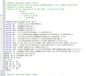
*6L6GC LTspice model based on the generic tetrode/pentode model from Adrian Immler, version i3f, Jan. 2020
*i3f means FIXED i3 version. The model works now also for selfbiased stages, cathode followers and the like.
*A version log is at the end of this file
*Params fitted to the GE datasheet by Adrian Immler, October 2019
*The high fit quality is presented at adrianimmler.simplesite.com
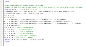
*This model is an enhancement of Adrians generic triode model to achieve tetrode/pentode behaviour.
*Hence, it is also suitable when the tetrode/pentode is "triode connected".
*Convenient for power beam as well as for small signal tetrodes/pentodes (just play with radl!).
*
* plate (in this model, "anode" means the internal virtual triode anode)
* | grid2
* | | grid1
* | | | cathode
* | | | |
.subckt 6L6GC_i3f P G2 G1 K
+ params:
*Parameters for the space charge current @ Vg <= 0
+ mu1 = 10 ;Determines the voltage gain @ constant Ia
+ rad = 1k21 ;Differential anode resistance, set @ Iad and Vg=0V
+ Vct = 0.97 ;Offsets the Ia-traces on the Va axis. Electrode material's contact potential
+ kp = 38 ;Mimics the island effect
+ xs = 1.4 ;Determines the curve of the Ia traces. Typically between 1.2 and 1.8
*
*Parameters for assigning the space charge current to Ia and Ig @ Vg > 0 and small Va
+ kB1 = 0.10 ;Describes how fast Ia drops to zero when Va approaches zero.
+ radl = 340 ;Differential resistance for the Ia emission limit @ very small Va and Vg > 0
+ tsh = 8 ;Ia transmission sharpness from 1th to 2nd Ia area. Keep between 3 and 20. Start with 20.
+ xl = 1.4 ;Exponent for the emission limit
*
*Parameters of the grid-cathode vacuum diode
+ Rg1i = 40 ;Internal grid1 resistor. Causes an Is reduction @ Ig > 0.
+ kg1 = 930 ;Inverse scaling factor for the Va independent part of Ig (caution - interacts with xg!)
+ Vctg1 = 1.2;Offsets the log Ig-traces on the Vg axis. Electrode material's contact potential
+ xg1 = 1.0 ;Determines the curve of the Ig slope versus (positive) Vg and Va >> 0
+ VT = 0.1 ;Log(Ig) slope @ Vg<0. VT=k/q*Tk (cathodes absolute temp, typically 1150K)
*
*Parameters for the caps
+ cg1p = 0p6 ;From datasheet
+ cg1All= 10p ;From datasheet
+ cpAll = 6p5 ;From datasheet
*
*Parameters to enhance the triode model to a pentode model
+ mu2 = 24 ;1/mu2 is the fraction of Vp which together with Vg2i builds the virtual Triode-Anode Voltage
+ kB2 = 0.25 ;Describes how fast Ip drops to zero when Vp approaches zero.
+ Rg2i = 200 ;Internal grid2 resistor. Causes an Is reduction when Ig2 increases while Vp drops
+ fr2 = 52m5 ;determines the residual ig2 fraction @ high Va values
+ ftfr2 = 1m2 ;if fr2 showes a Vg2 dependancy, this can be considered with this parameter
*
*Parameters to mimic the secondary emission (inspired from Derk Reefmans approach)
+ co = 0.9 ;decribes the crossover region (Ise drop when Va increase). between 0 and 9
+ Vse=65 a=0 ;Va where the sec. emission is strongest. a=related Vg1 coefficient
+ Ise0=2m2 b=0.22m ;sec. emission peak current @ Vg=0. b=related Vg1 coefficient
+ Vg2ref = 250 ;Vg2 where the following coeffficients has no influence to the emission effect:
+ c = 4m ;Vg2 coefficient of a
+ d = 7.7m ;exp Vg2 coefficient of Ise0
+ e = -0.8u ;Vg2 coeff. of b
*
*Calculated parameters
+ Iad = 100/rad ;Ia where the anode a.c. resistance is set according to rad.
+ ks = pow(mu1/(rad*xs*Iad**(1-1/xs)),-xs) ;Reduces the unwished xs influence to the Ia slope
+ ksnom = pow(mu1/(rad*1.5*Iad**(1-1/1.5)),-1.5) ;Sub-equation for calculating Vg0
+ Vg0 = Vct + (Iad*ks)**(1/xs) - (Iad*ksnom)**(2/3) ;Reduces the xs influence to Vct.
+ kl = pow(1/(radl*xl*Ild**(1-1/xl)),-xl) ;Reduces the xl influence to the Ia slope @ small Va
+ Ild = sqrt(radl)*1m ;Current where the limited anode a.c. resistance is set according to radl.
*
*Space charge current model
Bggi GG1i 0 V=v(G1i,K)+Vg0 ;Effective internal grid voltage.
Bahc Ahc 0 V=uramp(v(P,K)/mu2+v(G2i,K)) ;voltage of the virtual triode anode, hard cut to zero
Bst St 0 V=max(v(GG1i)+v(Ahc)/(mu1), v(Ahc)/kp*ln(1+exp(kp*(1/mu1+v(GG1i)/(1+v(Ahc))))));Steering volt.
Bs Ai K I=ft1()/ks*pow(v(St),xs) ;Langmuir-Childs law for the space charge current Is
.func ft1() {1+(1+tanh(4*v(GG1i)))/38} ;Finetuning-function for better overall fit at pos Vg
*
*Anode current limit @ small Va
.func smin(w,y,n) {pow(pow(w+1f, -n)+pow(y+1f, -n), -1/n)} ;Min-function with smooth trans.
Ra A Ai 1
Bpl G2i P I=i(Rp) - smin(1/kl*pow(v(P,K),xl),i(Rp),tsh);Ia emission limit
*
*Grid model
Rg1i G1 G1i {Rg1i} ;Internal grid resistor for "Ia-reduction" @ Vg > 0
.func Ivd(Vvd, kvd, xvd, VTvd) {1/kvd*pow(VTvd*xvd*ln(1+exp(Vvd/VTvd/xvd)),xvd)} ;Vacuum diode function
Bg1vd G1 K I=Ivd(v(G1,K)+Vctg1-1m*sqrt(v(Ahc)), kg1, xg1, VT) ;Grid-cathode vacuum diode
.func ft2() {7*(1-tanh(3*(v(G1,K)+Vg0)))} ;Finetuning-func. improves ig-fit @ Vg near -0.5V, low Va.
Bg1r G1i Ai I=ft1()*ivd(v(GG1i),ks, xs, 0.8*VT)/(1+ft2()+kB1*v(Ahc));Is reflection to grid when Va appr. zero
Bs0 Ai K I=ft1()*ivd(v(GG1i),ks, xs, 0.8*VT)/(1+ft2()) - ft1()/ks*pow(v(GG1i),xs) ;Compensates neg Ia
*@ small Va and Vg near zero
*
*additional model parts necessary for a pentode
Rg2i G2 G2i {Rg2i}
Rp P A 1
Bg2r G2i A I=i(Ra)*((1-frg2())/(1+kB2*max(0,v(P,K))) ) ; Va dependable ig2 part, reflected from the plate
Bg2f G2 A I=i(Ra)*frg2() ; Va independable ig2 part. Not to lead this current over Rg2i improves convergence
.func frg2() {fr2*exp(ftfr2*(v(G2,K)-250))}
*model for secondary emission effect
*nomalizing function nf(sh) ensures that the peak of y=x*(1-tanh(sh(x-1)) is always at x=1 while sh=0..9
.func nf(z) {609m/z + 293m + 107m*z - 5.71m*z*z}
.func sh() {pow(co,2)} ;results in a more linear control of the cross over region with the param co
Bsee G2 P I=Ise()*nf(sh())*x()*(1-tanh(sh()*(nf(sh())*x()-1))) / (nf(sh())*(1-tanh(sh()*(nf(sh())-1))))
.func Ise() {smin(uramp(Isef() - bf()*v(G1,K)),0.98*i(Rp),2)} ;avoides neg. Iplate caused by strong sec. em.
.func x() {v(P,K)/(1m+uramp(Vse-af()*v(G1,K)))}; moves the sec emission peak to the wanted voltage Vsep
.func af() {a + c*(v(G2,K)-Vg2ref)}
.func Isef() {Ise0 * exp(d*(v(G2,K)-Vg2ref))}
.func bf() {b + e*((v(G2,K)-Vg2ref))}
*
*Caps
C1 G1 P {cg1p} ;from datasheet
C2 G1 K {cg1All/2} ;most datasheets gives a cap "g1 to all except plate". As this model does not consider the
*heater or the ambient as further electrodes for parasitic caps, best way is to assume this " g1 to all" cap
*as it would be half to cathode and half to g2.
C3 G1 G2 {cg1All/2}
C4 P K {cpAll/2} ;most datasheets gives a cap "plate to all except g1". As this model does not consider the
*heater or the ambient as further electrodes for parasitic caps, best way is to assume this " plate to all" cap
*as it would be half to cathode and half to g2.
C5 P G2 {cpAll/2}
.ends
*
*Version log
*i1 :Initial version
*i2 :Pin order changed to the more common order "P G2 G1 K" (Thanks to Markus Gyger for his tip)
*i3 :residual ig2 @ large Va introduced; 2nd emission effect introduced; Va indep. grid current parts no longer lead over internal grid resistors for better convergence
*i3f : Major Bug Fixed. Some Grid/Plate voltages has been refered to GND instead of cathodeI wrapped curly braces around the equations in the Calculated parameters section and the duplicate definition errors went away. Modified this way your i2 models will run fine in MC12, but the i3 and i4 models have a host of other issues in MC12 such as:Hi Adrian.
Here's the error I get when trying to run your 6L6GC_i3f model in Micro-Cap 12.
Error: Duplicate definition for ( RAD*XS*IAD**.
Error: Floating point 'Multiple Traps' (0xc00002b5)
but still work in LTspice with no problems as I've been able to determine so far.
Code:
*Calculated parameters
+ Iad = {100/rad} ;Ia where the anode a.c. resistance is set according to rad.
+ ks = {pow(mu1/(rad*xs*Iad**(1-1/xs)),-xs)} ;Reduces the unwished xs influence to the Ia slope
+ ksnom = {pow(mu1/(rad*1.5*Iad**(1-1/1.5)),-1.5)} ;Sub-equation for calculating Vg0
+ Vg0 = {Vct + (Iad*ks)**(1/xs) - (Iad*ksnom)**(2/3)} ;Reduces the xs influence to Vct.
+ kl = {pow(1/(radl*xl*Ild**(1-1/xl)),-xl)} ;Reduces the xl influence to the Ia slope @ small Va
+ Ild = {sqrt(radl)*1m} ;Current where the limited anode a.c. resistance is set according to radl.
*Are thee models the same for the Russian 6n7?Code:* ============================================================== * 6N7_GE Twin triode power amplifier LTSpice model * Modified Koren model (8 parameters): mean fit error 0.059444mA * Traced by Wayne Clay on 9/6/2007 using Curve Captor v0.9.1 * from General Electric data sheet * Note: Positive grid region not modeled * Inter-electrode capacitances are guesses * ============================================================== .subckt 6N7_GE P G K Bp P K I= + (0.0114397703m)*uramp(V(P,K)*ln(1.0+(-0.5370300777)+exp((7.042163077)+ + (7.042163077)*((40.286562)+(476.0498871m)*V(G,K))*V(G,K)/sqrt((1.127269255)**2+ + (V(P,K)-(-24.1176161))**2)))/(7.042163077))**(1.290144231) Cgk G K 4p Cgp G P 4p Cpk P K 3p .ends 6N7_GE
6N7S? They appear to be. Below is a model for the 6N7S in the low current region, below 20mA. Positive grid region is not modeled.Are thee models the same for the Russian 6n7?
Code:
* ==============================================================
* 6N7S LTSpice model
* Koren model (5 parameters): mean fit error 0.264943mA
* Traced by Wayne Clay on 12/26/2019 using Curve Captor v0.9.1
* and Engauge Digitizer 10.4 from Soviet datasheet
* ==============================================================
.subckt 6N7S  P G K
    Bp  P K  I=(0.01068292927m)*uramp(V(P,K)*ln(1.0+exp((7.196465919)+
+ (7.196465919)*(37.98500662)*V(G,K)/sqrt((0.07628267106k)+
+ (V(P,K))**2)))/(7.196465919))**(1.312942692)
    Cgp G P 2.4p ; 0.0p added (2.4p)
    Cgk G K 4.3p ; 0.0p added (4.3p)
    Cpk P K 5.4p ; 0.0p added (5.4p)
    Rpk P K 1.0G ; to avoid floating nodes
    d3  G K dx1
.model dx1 d(is=1n rs=2k cjo=1pf N=1.5 tt=1n)
.ends 6N7SThank you sir!6N7S? They appear to be. Below is a model for the 6N7S in the low current region, below 20mA. Positive grid region is not modeled.
Code:* ============================================================== * 6N7S LTSpice model * Koren model (5 parameters): mean fit error 0.264943mA * Traced by Wayne Clay on 12/26/2019 using Curve Captor v0.9.1 * and Engauge Digitizer 10.4 from Soviet datasheet * ============================================================== .subckt 6N7S P G K Bp P K I=(0.01068292927m)*uramp(V(P,K)*ln(1.0+exp((7.196465919)+ + (7.196465919)*(37.98500662)*V(G,K)/sqrt((0.07628267106k)+ + (V(P,K))**2)))/(7.196465919))**(1.312942692) Cgp G P 2.4p ; 0.0p added (2.4p) Cgk G K 4.3p ; 0.0p added (4.3p) Cpk P K 5.4p ; 0.0p added (5.4p) Rpk P K 1.0G ; to avoid floating nodes d3 G K dx1 .model dx1 d(is=1n rs=2k cjo=1pf N=1.5 tt=1n) .ends 6N7S
Modified this way your i2 models will run fine in MC12, but the i3 and i4 models have a host of other issues in MC12 such as:
Error: Floating point 'Multiple Traps' (0xc00002b5)
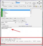
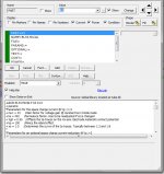
Hello I have made the modifications that you indicate for MC12, of the EL33 tube. The tube response is as in the image. Issues the error in the box below. In Adrian Immler's original file "only" ends in ".end", I have included the expression as in ".subckt" but it still doesn't work. What can be the error? Thank you.
Attachments
Hello I have made the modifications that you indicate for MC12, of the EL33 tube. The tube response is as in the image. Issues the error in the box below. In Adrian Immler's original file "only" ends in ".end", I have included the expression as in ".subckt" but it still doesn't work. What can be the error? Thank you.
Hi Pillo69,
Perhaps MC has a problem with the point in the spice model name, as points are used to introduce a command. Why not do a trial without the point in the spice model name?
- Home
- Amplifiers
- Tubes / Valves
- Vacuum Tube SPICE Models