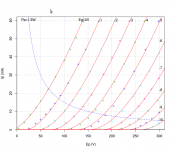
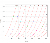
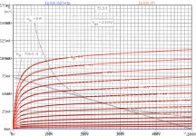
Yes, it's much harder to bend the grid current parameters around to make the painted graph similar to the datasheet graph, but it can be done reasonably over the range you anticipate operating, with a bit of effort. Many datasheets have little data on the topic anyway.
His basic paint tool is very easy to operate and everyone should have a go as it is very satisfying to get a good curve fit.
kind regards
Marek
His basic paint tool is very easy to operate and everyone should have a go as it is very satisfying to get a good curve fit.
kind regards
Marek
Hello guys, again,
it has turn out, that i've mistakenly thought, that i've got LTspice model for tube E88CC.
After second check, i've seen, that is ECC88.
Would it be possible to post that E88CC Spice model?
This is the last one, i swear(for now)
Code:
*
* Generic triode model: E88CC_Te_AN (Tesla)
* Copyright 2003--2008 by Ayumi Nakabayashi, All rights reserved.
* Version 3.10, Generated on Wed Dec 26 22:45:53 2018
*                Plate
*                | Grid
*                | | Cathode
*                | | |
.SUBCKT E88CC_AN A G K
BGG   GG   0 V=V(G,K)+0.29815813
BM1   M1   0 V=(0.0087052398*(URAMP(V(A,K))+1e-10))**-0.45632922
BM2   M2   0 V=(0.76674211*(URAMP(V(GG)+URAMP(V(A,K))/26.795113)+1e-10))**1.9563292
BP    P    0 V=0.0068223047*(URAMP(V(GG)+URAMP(V(A,K))/34.946708)+1e-10)**1.5
BIK   IK   0 V=U(V(GG))*V(P)+(1-U(V(GG)))*0.0039636404*V(M1)*V(M2)
BIG   IG   0 V=0.0034111523*URAMP(V(G,K))**1.5*(URAMP(V(G,K))/(URAMP(V(A,K))+URAMP(V(G,K)))*1.2+0.4)
BIAK  A    K I=URAMP(V(IK,IG)-URAMP(V(IK,IG)-(0.0037060676*URAMP(V(A,K))**1.5)))+1e-10*V(A,K)
BIGK  G    K I=V(IG)
* CAPS
CGA   G    A 1.4p
CGK   G    K 3.1p
CAK   A    K 0.5p
.ENDS
Attachments
6922 models
Here are two 6922 models I cooked up some time ago from the Raytheon datasheet for your simulation pleasure(s).
Here are two 6922 models I cooked up some time ago from the Raytheon datasheet for your simulation pleasure(s).
Code:
* ==============================================================
* 6922 LTspice model
* Modified Koren model (8 parameters) mean fit error 0.333943mA
* Traced by Wayne Clay on 05/29/2016 using Curve Captor v0.9.1
* and Engauge Digitizer from Raytheon data sheet (low current region)
* ==============================================================
.subckt 6922  P G K
    Bp  P K  I=
+ (0.08796398672m)*uramp(V(P,K)*ln(1.0+(-0.2246171356)+exp((6.356515287)+
+ (6.356515287)*((34.07615547)+(302.8072861m)*V(G,K))*V(G,K)/sqrt((41.2072838)**2+
+ (V(P,K)-(5.251577024))**2)))/(6.356515287))**(1.317210472)
    Cgp G P 2.3p ; 0.7p added
    Cgk G K 4.6p ; 0.7p added
    Cpk P K 2.15p ; 0.2p added
    Rpk P K 1G ; to avoid floating nodes
    d3  G K dx1
.model dx1 d(is=1n rs=2k cjo=1pf N=1.5 tt=1n)
.ends 6922
Code:
* ==============================================================
* Raytheon low current region
* Generic triode model: 6922_AN
* Copyright 2003--2008 by Ayumi Nakabayashi, All rights reserved.
* Version 3.10, Generated on Tue Aug 21 19:33:42 2018
*               Plate
*               | Grid
*               | | Cathode
*               | | |
.SUBCKT 6922_AN A G K
BGG   GG   0 V=V(G,K)+0.21627812
BM1   M1   0 V=(0.011598789*(URAMP(V(A,K))+1e-10))**-0.63489245
BM2   M2   0 V=(0.70261151*(URAMP(V(GG)+URAMP(V(A,K))/25.639617)+1e-10))**2.1348925
BP    P    0 V=0.0077467018*(URAMP(V(GG)+URAMP(V(A,K))/36.491883)+1e-10)**1.5
BIK   IK   0 V=U(V(GG))*V(P)+(1-U(V(GG)))*0.0044880083*V(M1)*V(M2)
BIG   IG   0 V=0.0038733509*URAMP(V(G,K))**1.5*(URAMP(V(G,K))/(URAMP(V(A,K))+URAMP(V(G,K)))*1.2+0.4)
BIAK  A    K I=URAMP(V(IK,IG)-URAMP(V(IK,IG)-(0.004193951*URAMP(V(A,K))**1.5)))+1e-10*V(A,K)
BIGK  G    K I=V(IG)
* CAPS
CGA   G    A 1.6p
CGK   G    K 3.9p
CAK   A    K 2p
.ENDS
Attachments
76 spice model
Code:
* ==============================================================
* 76_TS LTSpice model
* Modified Koren model (8 parameters): mean fit error 0.100442mA
* Traced by Wayne Clay using PlotDigitizer and Curve Captor v0.9.1
* from Tung-Sol data sheet
* ==============================================================
.subckt 76_TS  P G K
    Bp  P K  I=
+ (0.02107115629m)*uramp(V(P,K)*ln(1.0+(-0.08965100473)+exp((13.53366263)+
+ (13.53366263)*((14.05551312)+(3.84684871m)*V(G,K))*V(G,K)/sqrt((25.662436)**2+
+ (V(P,K)-(-1.165574625))**2)))/(13.53366263))**(1.323073242)
  Cgp G P 3.0p ; 0.2p added (2.8p)
  Cgk G K 3.8p ; 0.2p added (3.6p)
  Cpk P K 2.8p ; 0.2p added (2.6p)
  Rpk P K 1G
  d3  G K dx1
.model dx1 d(is=1n rs=2k cjo=1pf N=1.5 tt=1n)
.ends 76_TS
Attachments
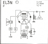
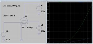
The EL3 is an audio output pentode from 1938. Ten years later the updated version was the EL3N that was functionally equivalent to the EL33 that was fitted with a standard IO base cap. I found data sheet of the EL33 Mullard, I hope that could help....all the best
Attachments
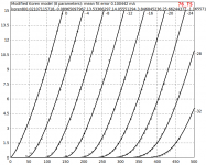
Hi Pillo69, hi kissabout2002
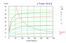
Thanks for uTracer curves and EL33 data sheet.
While the uTracer curve tells us Ia=61mA @ Va=100V, the data sheet says it should be 97mA. So that means that the given EL3N sample seems to have a quite reduced emission capability. Perhaps it has run already a long time?
How ever:
@ Pillo69, what would you prefer, a spice model according your uTracer curve or according the EL33 data sheet?
If uTracer, may you do additional measurements for the grid currents?
all the best, Adrian
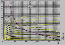
Hi Pillo69, hi Zung
here is my EL33 model. It turned out that my model can't fit both modes well (standard mode and triode connected), so I decided to optimize for standard mode.
And Ig1 behavior is estimated by comparison with other power pentodes, so don't expect to much accuracy for Ig1.
all the best, Adrian
here is my EL33 model. It turned out that my model can't fit both modes well (standard mode and triode connected), so I decided to optimize for standard mode.
And Ig1 behavior is estimated by comparison with other power pentodes, so don't expect to much accuracy for Ig1.
all the best, Adrian
Code:
*EL33 LTspice model based on the generic tetrode/pentode model from Adrian Immler, version i4, May 2020
*Be aware that the iG1 model is just guessed due to lack of iG1 data!!
*A version log is at the end of this file
*Params fitted to Telefunken datasheet by Adrian Immler, May 2020
*This model is an enhancement of Adrians generic triode model to achieve tetrode/pentode behaviour.
*Hence, it is also suitable when the tetrode/pentode is "triode connected".
*Convenient for tetrodes, power beam tetrodes and g3-grounded pentodes.
*Copes secondary emission effect!
*            MU=Mullard
*            | version i4
*            | | p=preliminary due to lack of iG1 data
*            | | | plate (in this model, "anode" means the internal virtual triode anode)
*            | | | | grid2
*            | | | | |  grid1
*            | | | | |  |  cathode
*            | | | | |  |  |
.subckt EL33.MUi4p P G2 G1 K
.params
*Parameters for the space charge current @ Vg <= 0
+ mu1 = 23      ;Main factor for voltage gain @ constant Ia in triode mode
+ ks = 342      ;Permeance factor. Has to be readjusted if xs is changed
+ Vg0 = 0.55    ;Offsets the Ia-traces on the Va axis. Electrode material's contact potential
+ kp = 150      ;Mimics the island effect
+ xs = 1.5      ;Determines the curve of the Ia traces. Typically between 1.2 and 1.8
*
*Parameters for an optional space charge current reduction @ Vg > 0
+ kIsr = 0.0    ;Va independable Is reduction, a function of Vg1
+ Rg1i = 10     ;Internal grid1 resistor which causes an extra Is drop when Va approaches zero.
*
*Parameters for assigning the space charge current to Ia and Ig @ Vg > 0 and small Va
+ kB1 = 0.1     ;Describes how fast Ia_virtual drops to zero when Va_virtual approaches zero.
+ radl = 10     ;Differential resistance for the Ia emission limit @ very small Va and Vg > 0
+ tsh = 8       ;Ia transmission sharpness from 1th to 2nd Ia area. Keep between 3 and 20. Start with 20.
+ xl = 1.3      ;Exponent for the emission limit
+ Vctl = 0 f=0  ;Offsets the Ia emission limit trace on the Va axis. f=related Vg1 koeff.
*
*Parameters of the grid-cathode vacuum diode
+ kg1 = 5k      ;estimated value!!
+ Vctg1 = 0.55  ;estimated value!!
+ xg1 = 1.5     ;Determines the curve of the Ig slope versus (positive) Vg and Va >> 0
+ VT = 0.1      ;Log(Ig) slope @ Vg<0. VT=k/q*Tk (cathodes absolute temp, typically 1150K)
*
*Parameters for the caps
+ cg1p  = 1p0   ;according datasheet
+ cg1All= 0p1   ;not mentioned in datasheet
+ CpAll = 0p1   ;not mentioned in datasheet
+ Cpk   = 0p1   ;not mentioned in datasheet
*
*Parameters to enhance the triode model to a pentode model
+ mu2 = 30      ;1/mu2 is the fraction of Vp which together with Vg2i builds the virtual Triode-Anode Voltage
+ kB2 = 0.1     ;Describes how fast Ip drops to zero when Vp approaches zero.
+ Rg2i = 10     ;Internal grid2 resistor. Causes an Is reduction when Ig2 increases while Vp drops
+ fr2 = 0.075   ;determines the residual ig2 fraction @ high Va values
+ ftfr2 = 0     ;if fr2 showes a Vg2 dependancy, this can be considered with this parameter
*
*Parameters to mimic the secondary emission (inspired from Derk Reefmans approach)
+ co = 1.4      ;decribes the crossover region (Ise drop when Va increase). between 0 and 9
+ Vse=60   a=0  ;Va where the sec. emission is strongest. a=related Vg1 coefficient
+ Ise0=0 b=0    ;sec. emission peak current @ Vg=0. b=related Vg1 coefficient
+ Vg2ref = 250  ;Vg2 where the following coeffficients has no influence to the emission effect:
+ c = 0         ;Vg2 coefficient of a
+ d = 0         ;exp Vg2 coefficient of Ise0
+ e = 0         ;Vg2 coeff. of b
*
*Calculated parameters
+ kl = pow(1/(radl*xl*Ild**(1-1/xl)),-xl) ;Reduces the xl influence to the Ia slope @ small Va
+ Ild = sqrt(radl)*1m ;Current where the limited anode a.c. resistance is set according to radl.
*
*Space charge current model
Bggi GG1i 0 V=v(G1i,K)+Vg0 - v(G1,K)*(1-1/(1+kIsr*max(0,v(G1,K)))) ;Effective internal grid voltage.
Bahc Ahc 0 V=uramp(v(P,K)/mu2+v(G2i,K)) ;voltage of the virtual triode anode, hard cut to zero
Bst St 0 V=max(v(GG1i)+v(Ahc)/(mu1), v(Ahc)/kp*ln(1+exp(kp*(1/mu1+v(GG1i)/(1+v(Ahc))))));Steering volt.
Bs Ai K I=1/ks*pow(v(St),xs) ;Langmuir-Childs law for the space charge current Is
*
*Anode current limit @ small Va
.func smin(x,y,n) {pow(pow(x + 1f, -n)+pow(y+1f, -n), -1/n)} ;Min-function with smooth trans.
Ra A Ai 1
Bpl G2i P I=i(Rp) - smin(1/kl*pow(v(P,K)+min(0,Vctl+f*v(G1,K)),xl),i(Rp),tsh);Ip emission limit
*
*Grid model
Rg1i G1 G1i {Rg1i} ;Internal grid resistor for "Ia-reduction" @ Vg > 0
.func Ivd(Vvd, kvd, xvd, VTvd) {1/kvd*pow(VTvd*xvd*ln(1+exp(Vvd/VTvd/xvd)),xvd)} ;Vacuum diode function
Bg1vd G1 K I=Ivd(v(G1,K)+Vctg1-1m*sqrt(v(Ahc)), kg1, xg1, VT) ;Grid-cathode vacuum diode
Bg1r G1i Ai I=ivd(v(GG1i),ks, xs, 0.8*VT)/(1+kB1*v(Ahc));Is reflection to grid when Va appr. zero
Bs0 Ai K I=ivd(v(GG1i),ks, xs, 0.8*VT) - 1/ks*pow(v(GG1i),xs) ;Compensates neg Ia
*@ small Va and Vg near zero
*
*additional model parts necessary for a pentode
Rg2i G2 G2i {Rg2i}
Rp P A 1
Bg2r G2i A I=i(Ra)*((1-frg2())/(1+kB2*max(0,v(P,K))) ) ; Va dependable ig2 part, reflected from the plate
Bg2f G2  A I=i(Ra)*frg2() ; Va independable ig2 part. Not to lead this current over Rg2i improves convergence
.func frg2() {fr2*exp(ftfr2*(v(G2,K)-250))}
*
*model for secondary emission effect
*nomalizing function nf(sh) ensures that the peak of y=x*(1-tanh(sh(x-1)) is always at x=1 while sh=0..9
.func nf(z) {609m/z + 293m + 107m*z - 5.71m*z*z}
.func sh() {pow(co,2)} ;results in a more linear control of the cross over region with the param co
Bsee G2 P I=min(Ise()*nf(sh())*xf()*(1-tanh(sh()*(nf(sh())*xf()-1))) / (nf(sh())*(1-tanh(sh()*(nf(sh())-1)))),i(Rp)-i(Bpl))
.func Ise() {smin(uramp(Isef() - bf()*v(G1,K)),0.98*i(Rp),2)} ;avoides neg. Iplate caused by strong sec. em.
.func xf() {v(P,K)/(1m+uramp(Vse-af()*v(G1,K)))}; moves the sec emission peak to the wanted voltage Vsep
.func af() {a + c*(v(G2,K)-Vg2ref)}
.func Isef()   {Ise0 * exp(d*(v(G2,K)-Vg2ref))}
.func bf()  {b + e*((v(G2,K)-Vg2ref))}
*
*Caps
C1 G1 P {cg1p}
C2 G1 K {(cg1All-cg1p)/2} ;As this model does not consider the ambient as further electrodes for parasitic caps,
;best way is to assume this " g1 to all" cap as it would be half to cathode and half to g2 (after substraction of cg1p).
C3 G1 G2 {(cg1All-cg1p)/2}
C4 P K {cpk}
C5 P G2 {cpAll-cpk-cg1p}
.end
*
*Version log
*i1 :Initial version
*i2 :Pin order changed to the more common order "P G2 G1 K" (Thanks to Markus Gyger for his tip)
*i3 :residual ig2 @ large Va introduced; 2nd emission effect introduced;
;Va indep. grid current parts no longer lead over internal grid resistors for better convergence
*i4 :to improve convegence, the Ia reduction @ pos Vg is no longer done by Rg1i. Instead, kIsr introduced
;Furthermore, ks and Vg0 are set directly, as rad and Vct turned out to be usefull for triodes only
*i4f :Major bug fixed. Tube works now also when Cathode not grounded (for cathode follower and the like)
Attachments
Hi Adrian,
Sorry disturb you but I try as an exercise to model this tube EL33, can you please check when you can no hurry this model, because I do not know if is right or not, I know you are very prepared in this matter....all the best
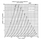
**** TEST ******************************************
* Created on 04/13/2020 17:55 using paint_kip.jar
* Model Paint Tools: Trace Tube Parameters over Plate Curves, Interactively
* Plate Curves image file:
* Data source link: <plate curves URL>
*----------------------------------------------------------------------------------
.SUBCKT EL33 P G2 G K ; LTSpice tetrode.asy pinout
* .SUBCKT TEST P G K G2 ; Koren Pentode Pspice pinout
+ PARAMS: MU=176 KG1=212.85 KP=129.14 KVB=86.4 VCT=6.496 EX=0.924 KG2=4158 KNEE=10.2 KVC=2.57
+ KLAM=6.5E-8 KLAMG=2.115E-4 KNK=-0.1023 KNG=0.00618
+ CCG=3P CGP=1.4P CCP=1.9P RGI=2360.0
* Vp_MAX=500 Ip_MAX=175 Vg_step=1 Vg_start=0 Vg_count=13
* X_MIN=51 Y_MIN=141 X_SIZE=711 Y_SIZE=496 FSZ_X=1296 FSZ_Y=776 XYGrid=true
* Rp=7000 Vg_ac=18.6 P_max=9 Vg_qui=-24 Vp_qui=505
* showLoadLine=y showIp=y isDHP=n isPP=n isAsymPP=n isUL=n showDissipLimit=y
* showIg1=n isInputSnapped=n addLocalNFB=n
* XYProjections=n harmonicPlot=n dissipPlot=n
* UL=0.43 EG2=250 gridLevel2=n addKink=n isTanhKnee=n advSigmoid=n
*----------------------------------------------------------------------------------
RE1 7 0 1G ; DUMMY SO NODE 7 HAS 2 CONNECTIONS
E1 7 0 VALUE= ; E1 BREAKS UP LONG EQUATION FOR G1.
+{V(G2,K)/KP*LOG(1+EXP((1/MU+(VCT+V(G,K))/SQRT(KVB+V(G2,K)*V(G2,K)))*KP))}
RE2 6 0 1G ; DUMMY SO NODE 6 HAS 2 CONNECTIONS
E2 6 0 VALUE={(PWR(V(7),EX)+PWRS(V(7),EX))} ; Kg1 times KIT current
G1 P K VALUE={V(6)/KG1*ATAN(V(P,K)/KNEE)*(1+KLAMG*V(P,K))+KLAM*V(P,K)}
* Alexander Gurskii screen current, see audioXpress 2/2011
RE4K 4K K 1G ; Dummy, per Alex request
E4K 4K 4 VALUE={0} ; Dummy, per Alex request
G4K 4K K VALUE={V(6)/KG2*(KVC-ATAN(V(P,K)/KNEE))/(1+KLAMG*V(P,K))}
RCP P K 1G ; FOR CONVERGENCE
C1 K G {CCG} ; CATHODE-GRID 1
C2 G P {CGP} ; GRID 1-PLATE
C3 K P {CCP} ; CATHODE-PLATE
R1 G 5 {RGI} ; FOR GRID CURRENT
D3 5 K DX ; FOR GRID CURRENT }
.MODEL DX D(IS=1N RS=1 CJO=10PF TT=1N)
.ENDS
*$
* The following triode model is derived from pentode model, see above.
* In the triode model, all spice parameters come directly from the pentode model, except for Kg1,
* which for triode-strapped pentodes is derived from pentode's Kg1, Kg2 and Kvc as
*
* 4Kg1Kg2 / ((2Kvc-Pi)(2Kg1+PiKg2))
**** TEST ******************************************
* Created on 04/13/2020 17:55 using paint_kit.jar 4.7
* Model Paint Tools: Trace Tube Parameters over Plate Curves, Interactively
* Plate Curves image file:
* Data source link: <plate curves URL>
*----------------------------------------------------------------------------------
.SUBCKT TRIODE_EL33 1 2 3 ; Plate Grid Cathode
+ PARAMS: CCG=3P CGP=1.4P CCP=1.9P RGI=2360
+ MU=176 KG1=131.33 KP=129.14 KVB=86.4 VCT=6.496 EX=0.924
* Vp_MAX=500 Ip_MAX=175 Vg_step=1 Vg_start=0 Vg_count=13
* Rp=7000 Vg_ac=18.6 P_max=9 Vg_qui=-24 Vp_qui=505
* X_MIN=51 Y_MIN=141 X_SIZE=711 Y_SIZE=496 FSZ_X=1296 FSZ_Y=776 XYGrid=true
* showLoadLine=y showIp=y isDHT=n isPP=n isAsymPP=n showDissipLimit=y
* showIg1=n gridLevel2=n isInputSnapped=n
* XYProjections=n harmonicPlot=n dissipPlot=n
*----------------------------------------------------------------------------------
E1 7 0 VALUE={V(1,3)/KP*LOG(1+EXP(KP*(1/MU+(VCT+V(2,3))/SQRT(KVB+V(1,3)*V(1,3)))))}
RE1 7 0 1G ; TO AVOID FLOATING NODES
G1 1 3 VALUE={(PWR(V(7),EX)+PWRS(V(7),EX))/KG1}
RCP 1 3 1G ; TO AVOID FLOATING NODES
C1 2 3 {CCG} ; CATHODE-GRID
C2 2 1 {CGP} ; GRID=PLATE
C3 1 3 {CCP} ; CATHODE-PLATE
D3 5 3 DX ; POSITIVE GRID CURRENT
R1 2 5 {RGI} ; POSITIVE GRID CURRENT
.MODEL DX D(IS=1N RS=1 CJO=10PF TT=1N)
.ENDS
*$
Sorry disturb you but I try as an exercise to model this tube EL33, can you please check when you can no hurry this model, because I do not know if is right or not, I know you are very prepared in this matter....all the best
**** TEST ******************************************
* Created on 04/13/2020 17:55 using paint_kip.jar
* Model Paint Tools: Trace Tube Parameters over Plate Curves, Interactively
* Plate Curves image file:
* Data source link: <plate curves URL>
*----------------------------------------------------------------------------------
.SUBCKT EL33 P G2 G K ; LTSpice tetrode.asy pinout
* .SUBCKT TEST P G K G2 ; Koren Pentode Pspice pinout
+ PARAMS: MU=176 KG1=212.85 KP=129.14 KVB=86.4 VCT=6.496 EX=0.924 KG2=4158 KNEE=10.2 KVC=2.57
+ KLAM=6.5E-8 KLAMG=2.115E-4 KNK=-0.1023 KNG=0.00618
+ CCG=3P CGP=1.4P CCP=1.9P RGI=2360.0
* Vp_MAX=500 Ip_MAX=175 Vg_step=1 Vg_start=0 Vg_count=13
* X_MIN=51 Y_MIN=141 X_SIZE=711 Y_SIZE=496 FSZ_X=1296 FSZ_Y=776 XYGrid=true
* Rp=7000 Vg_ac=18.6 P_max=9 Vg_qui=-24 Vp_qui=505
* showLoadLine=y showIp=y isDHP=n isPP=n isAsymPP=n isUL=n showDissipLimit=y
* showIg1=n isInputSnapped=n addLocalNFB=n
* XYProjections=n harmonicPlot=n dissipPlot=n
* UL=0.43 EG2=250 gridLevel2=n addKink=n isTanhKnee=n advSigmoid=n
*----------------------------------------------------------------------------------
RE1 7 0 1G ; DUMMY SO NODE 7 HAS 2 CONNECTIONS
E1 7 0 VALUE= ; E1 BREAKS UP LONG EQUATION FOR G1.
+{V(G2,K)/KP*LOG(1+EXP((1/MU+(VCT+V(G,K))/SQRT(KVB+V(G2,K)*V(G2,K)))*KP))}
RE2 6 0 1G ; DUMMY SO NODE 6 HAS 2 CONNECTIONS
E2 6 0 VALUE={(PWR(V(7),EX)+PWRS(V(7),EX))} ; Kg1 times KIT current
G1 P K VALUE={V(6)/KG1*ATAN(V(P,K)/KNEE)*(1+KLAMG*V(P,K))+KLAM*V(P,K)}
* Alexander Gurskii screen current, see audioXpress 2/2011
RE4K 4K K 1G ; Dummy, per Alex request
E4K 4K 4 VALUE={0} ; Dummy, per Alex request
G4K 4K K VALUE={V(6)/KG2*(KVC-ATAN(V(P,K)/KNEE))/(1+KLAMG*V(P,K))}
RCP P K 1G ; FOR CONVERGENCE
C1 K G {CCG} ; CATHODE-GRID 1
C2 G P {CGP} ; GRID 1-PLATE
C3 K P {CCP} ; CATHODE-PLATE
R1 G 5 {RGI} ; FOR GRID CURRENT
D3 5 K DX ; FOR GRID CURRENT }
.MODEL DX D(IS=1N RS=1 CJO=10PF TT=1N)
.ENDS
*$
* The following triode model is derived from pentode model, see above.
* In the triode model, all spice parameters come directly from the pentode model, except for Kg1,
* which for triode-strapped pentodes is derived from pentode's Kg1, Kg2 and Kvc as
*
* 4Kg1Kg2 / ((2Kvc-Pi)(2Kg1+PiKg2))
**** TEST ******************************************
* Created on 04/13/2020 17:55 using paint_kit.jar 4.7
* Model Paint Tools: Trace Tube Parameters over Plate Curves, Interactively
* Plate Curves image file:
* Data source link: <plate curves URL>
*----------------------------------------------------------------------------------
.SUBCKT TRIODE_EL33 1 2 3 ; Plate Grid Cathode
+ PARAMS: CCG=3P CGP=1.4P CCP=1.9P RGI=2360
+ MU=176 KG1=131.33 KP=129.14 KVB=86.4 VCT=6.496 EX=0.924
* Vp_MAX=500 Ip_MAX=175 Vg_step=1 Vg_start=0 Vg_count=13
* Rp=7000 Vg_ac=18.6 P_max=9 Vg_qui=-24 Vp_qui=505
* X_MIN=51 Y_MIN=141 X_SIZE=711 Y_SIZE=496 FSZ_X=1296 FSZ_Y=776 XYGrid=true
* showLoadLine=y showIp=y isDHT=n isPP=n isAsymPP=n showDissipLimit=y
* showIg1=n gridLevel2=n isInputSnapped=n
* XYProjections=n harmonicPlot=n dissipPlot=n
*----------------------------------------------------------------------------------
E1 7 0 VALUE={V(1,3)/KP*LOG(1+EXP(KP*(1/MU+(VCT+V(2,3))/SQRT(KVB+V(1,3)*V(1,3)))))}
RE1 7 0 1G ; TO AVOID FLOATING NODES
G1 1 3 VALUE={(PWR(V(7),EX)+PWRS(V(7),EX))/KG1}
RCP 1 3 1G ; TO AVOID FLOATING NODES
C1 2 3 {CCG} ; CATHODE-GRID
C2 2 1 {CGP} ; GRID=PLATE
C3 1 3 {CCP} ; CATHODE-PLATE
D3 5 3 DX ; POSITIVE GRID CURRENT
R1 2 5 {RGI} ; POSITIVE GRID CURRENT
.MODEL DX D(IS=1N RS=1 CJO=10PF TT=1N)
.ENDS
*$
Attachments
Hi Adrian. I have an interesting problem. I am running two 6SN7s in parallel (a-a, g-g, k-k). I am also using a Constant Current Source for the plate load. I notice that when I move the bias point away from the 0Volts end of the curves, the harmonic distortion becomes much less. This seems to me to be counter-intuitive, but that's the way the sim turns out. I am at -9 Volts in this simulation, using Ayumi's model. It is also true for just one single half of the 6SN7, but better distortion figures for two in parallel. And with one tube, I run up against the supply voltage sooner, which is like a brick wall on the sine wave.
("you are welcome!" in Swiss German)
What I would really like to see is a set of curves for the two paralleled triodes, as if it were one single tube. Is there any way that I could draw out this theoretical graph? It would be very interesting.
Attachments
- Home
- Amplifiers
- Tubes / Valves
- Vacuum Tube SPICE Models