EF54 model
Looking for EF54 spice (LTspice) model. Triode or pentode.
https://bms.isjtr.ro/sheets/154/e/EF54.pdf
Looking for EF54 spice (LTspice) model. Triode or pentode.
https://bms.isjtr.ro/sheets/154/e/EF54.pdf
...sorry, I have to focus on other things the next 2-3 weeks. But perhaps mogliaa or someone else can create an EF54 model for you?Looking for EF54 spice (LTspice) model.
Looking for EF54 spice (LTspice) model. Triode or pentode.
https://bms.isjtr.ro/sheets/154/e/EF54.pdf
Still looking....
I know this this is about vacuum tubes only, but I did not get any response so far in the speakers forum, hope for better luck here:
Spice Model for Multi-Way Loudspeakers
I have been using this model which I found on the web somewhere.
It seems to be 3-way 8 ohm nominal.
But now I need 4 ohm, 6 ohm.
I don't think there is a simple way to convert it to 4 or 6 ohm.
Does somebody have a 4 or 6 ohm model willing to share it ?
2-way also welcome ... Thank you ...
* generic speaker simulation (8 ohm)
* as published in Stereophile Magazine.
*
* Donated by Jaime Arbona, converted to subcircuit form
.SUBCKT SPEAKER G $N_0002
R_R29 $N_0002 $N_0001 8
R_R30 $N_0003 $N_0002 5
R_R31 $N_0004 $N_0002 5.6
C_C9 $N_0001 $N_0005 4.7uf
C_C10 $N_0003 G 3.3uf
R_R32 $N_0006 $N_0005 0.5
L_L16 $N_0004 $N_0007 0.5mH
R_R33 $N_0009 $N_0008 100
R_R34 $N_0008 G 39
R_R35 $N_0008 $N_0010 0.6
R_R36 $N_0008 $N_0011 0.9
L_L17 $N_0011 $N_0009 1mH
L_L18 $N_0010 G 10mH
R_R37 $N_0009 $N_0007 0.7
L_L19 $N_0006 G 0.3mH
C_C11 $N_0008 G 500uf
.ENDS
Last edited:
Type 37:
* 37 LTSpice model 0.11ma
.subckt 37T P G K
Bp P K I=(0.01660894408m)*uramp(V(P,K)*ln(1.0+(-0.1930374759)+exp((3.923658596)+(3.923658596)*((9.577557755)+(-29.45086982m)*V(G,K))*V(G,K)/sqrt((40.57004746)**2+(V(P,K)-(13.9447219))**2)))/(3.923658596))**(1.401230164)
Cgp G P 2p
Cgk G K 3.5p
Cpk P K 2p
Rpk P K 1G
d3 G K dx1
.model dx1 d(is=1n rs=2k cjo=1pf N=1.5 tt=1n)
.ends 37
Looking for 6BW6 tube
Hi panos29
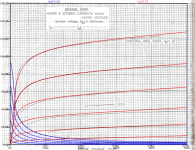
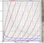
I'm happy to have found some rudimentary g1 current curves in the Brimar data sheet from 1952 - so I will start to develop a 6BW6 model, but it will need some days.
all the best, Adrian
Hi panos29
I'm happy to have found some rudimentary g1 current curves in the Brimar data sheet from 1952 - so I will start to develop a 6BW6 model, but it will need some days.
all the best, Adrian
Thank you dear! Actually I have a lot of cv4043 which are similar to 6bw6 and would love to use these in some way!
Hi panos29
here you go...
My freshly baked 6BW6 model!
all the best, Adrian
here you go...
My freshly baked 6BW6 model!
all the best, Adrian
Code:
*6BW6 LTspice model based on the generic tetrode/pentode model from Adrian Immler, version i3, Febr. 2020
*A version log is at the end of this file
*Params fitted to the Brimar datasheet by Adrian Immler, Febr. 2020
*The high fit quality is presented at adrianimmler.simplesite.com
*This model is an enhancement of Adrians generic triode model to achieve tetrode/pentode behaviour.
*Hence, it is also suitable when the tetrode/pentode is "triode connected".
*Convenient for power beam as well as for small signal tetrodes/pentodes.
*
*                 plate (in this model, "anode" means the internal virtual triode anode)
*                 | grid2
*                 | |  grid1
*                 | |  |  cathode
*                 | |  |  |
.subckt 6BW6.BRi3 P G2 G1 K
.params
*Parameters for the space charge current @ Vg <= 0
+ mu1 = 9.6  ;Determines the voltage gain @ constant Ia
+ rad = 2k05 ;Differential anode resistance, set @ Iad and Vg=0V
+ Vct = 0.85 ;Offsets the Ia-traces on the Va axis. Electrode material's contact potential
+ kp = 65    ;Mimics the island effect
+ xs = 1.5   ;Determines the curve of the Ia traces. Typically between 1.2 and 1.8
*
*Parameters for assigning the space charge current to Ia and Ig @ Vg > 0 and small Va
+ kB1 = 0.11 ;Describes how fast Ia drops to zero when Va approaches zero.
+ radl = 240 ;Differential resistance for the Ia emission limit @ very small Va and Vg > 0
+ tsh = 20   ;Ia transmission sharpness from 1th to 2nd Ia area. Keep between 3 and 20. Start with 20.
+ xl = 1.6   ;Exponent for the emission limit
*
*Parameters of the grid-cathode vacuum diode
+ Rg1i = 250  ;Internal grid1 resistor. Causes an Is reduction @ Ig > 0.
+ kg1 = 10k5  ;Inverse scaling factor for the Va independent part of Ig (caution - interacts with xg!)
+ Vctg1 = 0.65;Offsets the log Ig-traces on the Vg axis. Electrode material's contact potential
+ xg1 = 1.5   ;Determines the curve of the Ig slope versus (positive) Vg and Va >> 0
+ VT = 0.1    ;Log(Ig) slope @ Vg<0. VT=k/q*Tk (cathodes absolute temp, typically 1150K)
*
*Parameters for the caps
+ cg1p = 0p6  ;From datasheet
+ cg1All= 8p5 ;From datasheet
+ cpAll = 7p5 ;From datasheet
*
*Parameters to enhance the triode model to a pentode model
+ mu2 = 22     ;1/mu2 is the fraction of Vp which together with Vg2i builds the virtual Triode-Anode Voltage
+ kB2 = 0.105  ;Describes how fast Ip drops to zero when Vp approaches zero.
+ Rg2i = 350   ;Internal grid2 resistor. Causes an Is reduction when Ig2 increases while Vp drops
+ fr2 = 4m     ;determines the residual ig2 fraction @ high Va values
+ ftfr2 = 0    ;if fr2 showes a Vg2 dependancy, this can be considered with this parameter
*
*Parameters to mimic the secondary emission (inspired from Derk Reefmans approach)
+ co = 0.9     ;decribes the crossover region (Ise drop when Va increase). between 0 and 9
+ Vse=65   a=0 ;Va where the sec. emission is strongest. a=related Vg1 coefficient
+ Ise0=0  b=0  ;sec. emission peak current @ Vg=0. b=related Vg1 coefficient
+ Vg2ref = 250 ;Vg2 where the following coeffficients has no influence to the emission effect:
+ c = 0        ;Vg2 coefficient of a
+ d = 0        ;exp Vg2 coefficient of Ise0
+ e = 0        ;Vg2 coeff. of b
*
*Calculated parameters
+ Iad = 100/rad ;Ia where the anode a.c. resistance is set according to rad.
+ ks = pow(mu1/(rad*xs*Iad**(1-1/xs)),-xs) ;Reduces the unwished xs influence to the Ia slope
+ ksnom = pow(mu1/(rad*1.5*Iad**(1-1/1.5)),-1.5) ;Sub-equation for calculating Vg0
+ Vg0 = Vct + (Iad*ks)**(1/xs) - (Iad*ksnom)**(2/3) ;Reduces the xs influence to Vct.
+ kl = pow(1/(radl*xl*Ild**(1-1/xl)),-xl) ;Reduces the xl influence to the Ia slope @ small Va
+ Ild = sqrt(radl)*1m ;Current where the limited anode a.c. resistance is set according to radl.
*
*Space charge current model
Bggi GG1i 0 V=v(G1i,K)+Vg0 ;Effective internal grid voltage.
Bahc Ahc 0 V=uramp(v(P,K)/mu2+v(G2i,K)) ;voltage of the virtual triode anode, hard cut to zero
Bst St 0 V=max(v(GG1i)+v(Ahc)/(mu1), v(Ahc)/kp*ln(1+exp(kp*(1/mu1+v(GG1i)/(1+v(Ahc))))));Steering volt.
Bs Ai K I=ft1()/ks*pow(v(St),xs) ;Langmuir-Childs law for the space charge current Is
.func ft1() {1+(1+tanh(4*v(GG1i)))/38} ;Finetuning-function for better overall fit at pos Vg
*
*Anode current limit @ small Va
.func smin(z,y,n) {pow(pow(z+1f, -n)+pow(y+1f, -n), -1/n)} ;Min-function with smooth trans.
Ra A Ai 1
Bpl G2i P I=i(Rp) - smin(1/kl*pow(v(P,K),xl),i(Rp),tsh);Ia emission limit
*
*Grid model
Rg1i G1 G1i {Rg1i} ;Internal grid resistor for "Ia-reduction" @ Vg > 0
.func Ivd(Vvd, kvd, xvd, VTvd) {1/kvd*pow(VTvd*xvd*ln(1+exp(Vvd/VTvd/xvd)),xvd)} ;Vacuum diode function
Bg1vd G1 K I=Ivd(v(G1,K)+Vctg1-1m*sqrt(v(Ahc)), kg1, xg1, VT) ;Grid-cathode vacuum diode
.func ft2() {7*(1-tanh(3*(v(G1,K)+Vg0)))} ;Finetuning-func. improves ig-fit @ Vg near -0.5V, low Va.
Bg1r G1i Ai I=ft1()*ivd(v(GG1i),ks, xs, 0.8*VT)/(1+ft2()+kB1*v(Ahc));Is reflection to grid when Va appr. zero
Bs0 Ai K I=ft1()*ivd(v(GG1i),ks, xs, 0.8*VT)/(1+ft2()) - ft1()/ks*pow(v(GG1i),xs) ;Compensates neg Ia
*@ small Va and Vg near zero
*
*additional model parts necessary for a pentode
Rg2i G2 G2i {Rg2i}
Rp P A 1
Bg2r G2i A I=i(Ra)*((1-frg2())/(1+kB2*max(0,v(P,K))) ) ; Va dependable ig2 part, reflected from the plate
Bg2f G2  A I=i(Ra)*frg2() ; Va independable ig2 part. Not to lead this current over Rg2i improves convergence
.func frg2() {fr2*exp(ftfr2*(v(G2,K)-250))}

*model for secondary emission effect
*nomalizing function nf(sh) ensures that the peak of y=x*(1-tanh(sh(x-1)) is always at x=1 while sh=0..9
.func nf(z) {609m/z + 293m + 107m*z - 5.71m*z*z}
.func sh() {pow(co,2)} ;results in a more linear control of the cross over region with the param co
Bsee G2 P I=Ise()*nf(sh())*x()*(1-tanh(sh()*(nf(sh())*x()-1))) / (nf(sh())*(1-tanh(sh()*(nf(sh())-1))))
.func Ise() {smin(uramp(Isef() - bf()*v(G1,K)),0.98*i(Rp),2)} ;avoides neg. Iplate caused by strong sec. em.
.func x() {v(P,K)/(1m+uramp(Vse-af()*v(G1,K)))}; moves the sec emission peak to the wanted voltage Vsep
.func af() {a + c*(v(G2,K)-Vg2ref)}
.func Isef()   {Ise0 * exp(d*(v(G2,K)-Vg2ref))}
.func bf()  {b + e*((v(G2,K)-Vg2ref))}
*
*Caps
C1 G1 P {cg1p} ;from datasheet
C2 G1 K {cg1All/2} ;most datasheets gives a cap "g1 to all except plate". As this model does not consider the
*heater or the ambient as further electrodes for parasitic caps, best way is to assume this " g1 to all" cap
*as it would be half to cathode and half to g2.
C3 G1 G2 {cg1All/2}
C4 P K {cpAll/2} ;most datasheets gives a cap "plate to all except g1". As this model does not consider the
*heater or the ambient as further electrodes for parasitic caps, best way is to assume this " plate to all" cap
*as it would be half to cathode and half to g2.
C5 P G2 {cpAll/2}
.end
*
*Version log
*i1 :Initial version
*i2 :Pin order changed to the more common order "P G2 G1 K" (Thanks to Markus Gyger for his tip)
*i3 :residual ig2 @ large Va introduced; 2nd emission effect introduced
    ;Va indep. grid current parts no longer lead over internal grid resistors for better convergence
Attachments
Hi I want to model a bias circuit for 2 6L6.
Do you think I should build the whole schematic in ltspice or maybe should I use a resistor as a load. To simulate the bias load.
Do you know how much current a bias of push pull el34 6L6 need to supply ?
Will the spice models take the bias into account also ?
Thank you.
Do you think I should build the whole schematic in ltspice or maybe should I use a resistor as a load. To simulate the bias load.
Do you know how much current a bias of push pull el34 6L6 need to supply ?
Will the spice models take the bias into account also ?
Thank you.
You 're welcome, rongon!Hey Adrian,
I whipped up a little test circuit using your 6BW6 model and everything worked great. No error messages, got a good sine wave out, all good. Thanks!
--
Hi FredericoHi I want to model a bias circuit for 2 6L6. (...)
To be honest, I'm not sure if I understand properly what your intention is.
When it comes to the question how much bias current a 6L6 push pull stage needs, I would simulate the hole output stage, including the phase inverter, output transformer, and speaker (simplified to a resistor), to get an impression of the output signal distortion due to the transitions from one tube to the other.
Low bias will increase the transition distortions, and high bias will reduce the max. output power - so its up to you to find a compromise you can agree with.
And yes, todays 6L6 model are able to predict well how real tubes will behave - except the manufacturing tolerances!
all the best, Adrian
...
Do you know how much current a bias of push pull el34 6L6 need to supply ?
...
It depends.
According to the original datasheet by RCA, the 6L6GC are rated to these "design-maximum values": Vp: 500V, Vg2: 450V, Pd: 30W. These are values NOT to be exceeded, even though a lot of guitar amp manufacturers wouldn't care less.
For Hifi, I ran my McIntosh MC240 at 66mA, for a dissipation of 28W, per tube, for 30+ years with the original RCA 6L6GC. No problem; the power transformer was a just little warm to the touch. I decided to retube 8 years ago; I used the "Winged C" (original St. Petersburg Svetlana) 6L6GC, and decided to turn down the bias a bit to 55mA just to be on the safe side; so now the Pd is 24W per tube. It still sounds good, still much, much better than the original factory setting.
For guitar, I run my Pignose GR60 with some Chinese 6L6 at 32mA.
Thank you.
I was asking if it is modeled in ltspice. Now I know it is modeled.
And if I can use it to simulate the current needed for the negative bias supply to the grids of a push pull.
But If you know the load in mA of the grids it will save me time.
As I would not simulate the whole power section.
Nice program.
Last edited:
- Home
- Amplifiers
- Tubes / Valves
- Vacuum Tube SPICE Models