Hi all
Please be aware that I discovered this week a major bug in my generic pentode spice models with version i3 and i4. All simulations with this models delivers correct results only in case of grounded cathodes. So no self-bias, cathode follower and the like possible!
But I have now fixed versions _i3f and _i4f to offer. (f means "fixed")
Here the code of the fixed 6L6GC model:
Here the code of the fixed 1j29b model:
all the best, Adrian
Please be aware that I discovered this week a major bug in my generic pentode spice models with version i3 and i4. All simulations with this models delivers correct results only in case of grounded cathodes. So no self-bias, cathode follower and the like possible!
But I have now fixed versions _i3f and _i4f to offer
. (f means "fixed")Here the code of the fixed 6L6GC model:
Code:
*6L6GC LTspice model based on the generic tetrode/pentode model from Adrian Immler, version i3f, Jan. 2020
*i3f means FIXED i3 version. The model works now also for selfbiased stages, cathode followers and the like.
*A version log is at the end of this file
*Params fitted to the GE datasheet by Adrian Immler, October 2019
*The high fit quality is presented at adrianimmler.simplesite.com
*This model is an enhancement of Adrians generic triode model to achieve tetrode/pentode behaviour.
*Hence, it is also suitable when the tetrode/pentode is "triode connected".
*Convenient for power beam as well as for small signal tetrodes/pentodes (just play with radl!).
*
*                 plate (in this model, "anode" means the internal virtual triode anode)
*                 | grid2
*                 | |  grid1
*                 | |  |  cathode
*                 | |  |  |
.subckt 6L6GC_i3f P G2 G1 K
.params
*Parameters for the space charge current @ Vg <= 0
+ mu1 = 10   ;Determines the voltage gain @ constant Ia
+ rad = 1k21 ;Differential anode resistance, set @ Iad and Vg=0V
+ Vct = 0.97 ;Offsets the Ia-traces on the Va axis. Electrode material's contact potential
+ kp = 38    ;Mimics the island effect
+ xs = 1.4   ;Determines the curve of the Ia traces. Typically between 1.2 and 1.8
*
*Parameters for assigning the space charge current to Ia and Ig @ Vg > 0 and small Va
+ kB1 = 0.10 ;Describes how fast Ia drops to zero when Va approaches zero.
+ radl = 340 ;Differential resistance for the Ia emission limit @ very small Va and Vg > 0
+ tsh = 8    ;Ia transmission sharpness from 1th to 2nd Ia area. Keep between 3 and 20. Start with 20.
+ xl = 1.4   ;Exponent for the emission limit
*
*Parameters of the grid-cathode vacuum diode
+ Rg1i = 40  ;Internal grid1 resistor. Causes an Is reduction @ Ig > 0.
+ kg1 = 930  ;Inverse scaling factor for the Va independent part of Ig (caution - interacts with xg!)
+ Vctg1 = 1.2;Offsets the log Ig-traces on the Vg axis. Electrode material's contact potential
+ xg1 = 1.0  ;Determines the curve of the Ig slope versus (positive) Vg and Va >> 0
+ VT = 0.1   ;Log(Ig) slope @ Vg<0. VT=k/q*Tk (cathodes absolute temp, typically 1150K)
*
*Parameters for the caps
+ cg1p = 0p6  ;From datasheet
+ cg1All= 10p ;From datasheet
+ cpAll = 6p5 ;From datasheet
*
*Parameters to enhance the triode model to a pentode model
+ mu2 = 24    ;1/mu2 is the fraction of Vp which together with Vg2i builds the virtual Triode-Anode Voltage
+ kB2 = 0.25  ;Describes how fast Ip drops to zero when Vp approaches zero.
+ Rg2i = 200  ;Internal grid2 resistor. Causes an Is reduction when Ig2 increases while Vp drops
+ fr2 = 52m5  ;determines the residual ig2 fraction @ high Va values
+ ftfr2 = 1m2 ;if fr2 showes a Vg2 dependancy, this can be considered with this parameter
*
*Parameters to mimic the secondary emission (inspired from Derk Reefmans approach)
+ co = 0.9          ;decribes the crossover region (Ise drop when Va increase). between 0 and 9
+ Vse=65   a=0      ;Va where the sec. emission is strongest. a=related Vg1 coefficient
+ Ise0=2m2  b=0.22m ;sec. emission peak current @ Vg=0. b=related Vg1 coefficient
+ Vg2ref = 250      ;Vg2 where the following coeffficients has no influence to the emission effect:
+ c = 4m            ;Vg2 coefficient of a
+ d = 7.7m          ;exp Vg2 coefficient of Ise0
+ e = -0.8u         ;Vg2 coeff. of b
*
*Calculated parameters
+ Iad = 100/rad ;Ia where the anode a.c. resistance is set according to rad.
+ ks = pow(mu1/(rad*xs*Iad**(1-1/xs)),-xs) ;Reduces the unwished xs influence to the Ia slope
+ ksnom = pow(mu1/(rad*1.5*Iad**(1-1/1.5)),-1.5) ;Sub-equation for calculating Vg0
+ Vg0 = Vct + (Iad*ks)**(1/xs) - (Iad*ksnom)**(2/3) ;Reduces the xs influence to Vct.
+ kl = pow(1/(radl*xl*Ild**(1-1/xl)),-xl) ;Reduces the xl influence to the Ia slope @ small Va
+ Ild = sqrt(radl)*1m ;Current where the limited anode a.c. resistance is set according to radl.
*
*Space charge current model
Bggi GG1i 0 V=v(G1i,K)+Vg0 ;Effective internal grid voltage.
Bahc Ahc 0 V=uramp(v(P,K)/mu2+v(G2i,K)) ;voltage of the virtual triode anode, hard cut to zero
Bst St 0 V=max(v(GG1i)+v(Ahc)/(mu1), v(Ahc)/kp*ln(1+exp(kp*(1/mu1+v(GG1i)/(1+v(Ahc))))));Steering volt.
Bs Ai K I=ft1()/ks*pow(v(St),xs) ;Langmuir-Childs law for the space charge current Is
.func ft1() {1+(1+tanh(4*v(GG1i)))/38} ;Finetuning-function for better overall fit at pos Vg
*
*Anode current limit @ small Va
.func smin(x,y,n) {pow(pow(x+1f, -n)+pow(y+1f, -n), -1/n)} ;Min-function with smooth trans.
Ra A Ai 1
Bpl G2i P I=i(Rp) - smin(1/kl*pow(v(P,K),xl),i(Rp),tsh);Ia emission limit
*
*Grid model
Rg1i G1 G1i {Rg1i} ;Internal grid resistor for "Ia-reduction" @ Vg > 0
.func Ivd(Vvd, kvd, xvd, VTvd) {1/kvd*pow(VTvd*xvd*ln(1+exp(Vvd/VTvd/xvd)),xvd)} ;Vacuum diode function
Bg1vd G1 K I=Ivd(v(G1,K)+Vctg1-1m*sqrt(v(Ahc)), kg1, xg1, VT) ;Grid-cathode vacuum diode
.func ft2() {7*(1-tanh(3*(v(G1,K)+Vg0)))} ;Finetuning-func. improves ig-fit @ Vg near -0.5V, low Va.
Bg1r G1i Ai I=ft1()*ivd(v(GG1i),ks, xs, 0.8*VT)/(1+ft2()+kB1*v(Ahc));Is reflection to grid when Va appr. zero
Bs0 Ai K I=ft1()*ivd(v(GG1i),ks, xs, 0.8*VT)/(1+ft2()) - ft1()/ks*pow(v(GG1i),xs) ;Compensates neg Ia
*@ small Va and Vg near zero
*
*additional model parts necessary for a pentode
Rg2i G2 G2i {Rg2i}
Rp P A 1
Bg2r G2i A I=i(Ra)*((1-frg2())/(1+kB2*max(0,v(P,K))) ) ; Va dependable ig2 part, reflected from the plate
Bg2f G2  A I=i(Ra)*frg2() ; Va independable ig2 part. Not to lead this current over Rg2i improves convergence
.func frg2() {fr2*exp(ftfr2*(v(G2,K)-250))}

*model for secondary emission effect
*nomalizing function nf(sh) ensures that the peak of y=x*(1-tanh(sh(x-1)) is always at x=1 while sh=0..9
.func nf(z) {609m/z + 293m + 107m*z - 5.71m*z*z}
.func sh() {pow(co,2)} ;results in a more linear control of the cross over region with the param co
Bsee G2 P I=Ise()*nf(sh())*x()*(1-tanh(sh()*(nf(sh())*x()-1))) / (nf(sh())*(1-tanh(sh()*(nf(sh())-1))))
.func Ise() {smin(uramp(Isef() - bf()*v(G1,K)),0.98*i(Rp),2)} ;avoides neg. Iplate caused by strong sec. em.
.func x() {v(P,K)/(1m+uramp(Vse-af()*v(G1,K)))}; moves the sec emission peak to the wanted voltage Vsep
.func af() {a + c*(v(G2,K)-Vg2ref)}
.func Isef()   {Ise0 * exp(d*(v(G2,K)-Vg2ref))}
.func bf()  {b + e*((v(G2,K)-Vg2ref))}
*
*Caps
C1 G1 P {cg1p} ;from datasheet
C2 G1 K {cg1All/2} ;most datasheets gives a cap "g1 to all except plate". As this model does not consider the
*heater or the ambient as further electrodes for parasitic caps, best way is to assume this " g1 to all" cap
*as it would be half to cathode and half to g2.
C3 G1 G2 {cg1All/2}
C4 P K {cpAll/2} ;most datasheets gives a cap "plate to all except g1". As this model does not consider the
*heater or the ambient as further electrodes for parasitic caps, best way is to assume this " plate to all" cap
*as it would be half to cathode and half to g2.
C5 P G2 {cpAll/2}
.end
*
*Version log
*i1 :Initial version
*i2 :Pin order changed to the more common order "P G2 G1 K" (Thanks to Markus Gyger for his tip)
*i3 :residual ig2 @ large Va introduced; 2nd emission effect introduced; Va indep. grid current parts no longer lead over internal grid resistors for better convergence
* i3f : Major Bug Fixed. Some Grid/Plate voltages has been refered to GND instead of cathode
Here the code of the fixed 1j29b model:
Code:
*1j29b LTspice model based on the generic tetrode/pentode model from Adrian Immler, version i4f, Jan. 2020
*i4f means FIXED i4 version. The model works now also for selfbiased stages, cathode followers and the like.
*Important assumptions: both heaters are in parallel, heater- = REF (0V), g3 is connected to heater-
*A version log is at the end of this file
*Params fitted to measured data from a sample by Adrian Immler, Nov. 2019
*fit graphs see Vacuum Tube SPICE Models
*This model is an enhancement of Adrians generic triode model to achieve tetrode/pentode behaviour.
*Hence, it is also suitable when the tetrode/pentode is "triode connected".
*Convenient for tetrodes, power beam tetrodes and g3-grounded pentodes.
*Copes secondary emission effect!
*
*                 plate (in this model, "anode" means the internal virtual triode anode)
*                 | grid2
*                 | |  grid1
*                 | |  |  cathode
*                 | |  |  |
.subckt 1j29b_i4f P G2 G1 K
.params
*Parameters for the space charge current @ Vg <= 0
+ mu1 = 12      ;Main factor for voltage gain @ constant Ia in triode mode
+ ks = 1k20     ;Permeance factor. Has to be readjusted if xs is changed
+ Vg0 = -0.75   ;Offsets the Ia-traces on the Va axis. Electrode material's contact potential
+ kp = 37       ;Mimics the island effect
+ xs = 1.68     ;Determines the curve of the Ia traces. Typically between 1.2 and 1.8
*
*Parameters for an optional space charge current reduction @ Vg > 0
+ kIsr = 0.16   ;Va independable Is reduction, a function of Vg1
+ Rg1i = 100    ;Internal grid1 resistor which causes an extra Is drop when Va approaches zero.
*
*Parameters for assigning the space charge current to Ia and Ig @ Vg > 0 and small Va
+ kB1 = 0.3     ;Describes how fast Ia_virtual drops to zero when Va_virtual approaches zero.
+ radl = 500    ;Differential resistance for the Ia emission limit @ very small Va and Vg > 0
+ tsh = 8       ;Ia transmission sharpness from 1th to 2nd Ia area. Keep between 3 and 20. Start with 20.
+ xl = 1.8      ;Exponent for the emission limit
+ Vctl = -1 f=-0.85;Offsets the Ia emission limit trace on the Va axis. f=related Vg1 koeff.
*
*Parameters of the grid-cathode vacuum diode
+ kg1 = 6k      ;Inverse scaling factor for the Va independent part of Ig (caution - interacts with xg!)
+ Vctg1 = -1.3  ;Offsets the log Ig-traces on the Vg axis. Electrode material's contact potential
+ xg1 = 1.9     ;Determines the curve of the Ig slope versus (positive) Vg and Va >> 0
+ VT = 0.127    ;Log(Ig) slope @ Vg<0. VT=k/q*Tk (cathodes absolute temp, typically 1150K)
*
*Parameters for the caps
+ cg1p  = 5f    ;according datasheet
+ cg1All= 5p    ;according datasheet
+ CpAll = 3p    ;according datasheet
+ Cpk  = 28f    ;according datasheet
*
*Parameters to enhance the triode model to a pentode model
+ mu2 = 80        ;1/mu2 is the fraction of Vp which together with Vg2i builds the virtual Triode-Anode Voltage
+ kB2 = 0.8       ;Describes how fast Ip drops to zero when Vp approaches zero.
+ Rg2i = 900      ;Internal grid2 resistor. Causes an Is reduction when Ig2 increases while Vp drops
+ fr2 = 25m       ;determines the residual ig2 fraction @ high Va values
+ ftfr2 = 30m     ;if fr2 showes a Vg2 dependancy, this can be considered with this parameter
*
*Parameters to mimic the secondary emission (inspired from Derk Reefmans approach)
+ co = 2          ;decribes the crossover region (Ise drop when Va increase). between 0 and 9
+ Vse=18   a=0    ;Va where the sec. emission is strongest. a=related Vg1 coefficient
+ Ise0=0m20 b=-70u;sec. emission peak current @ Vg=0. b=related Vg1 coefficient
+ Vg2ref = 45     ;Vg2 where the following coeffficients has no influence to the emission effect:
+ c = 0           ;Vg2 coefficient of a
+ d = 40m         ;exp Vg2 coefficient of Ise0
+ e = 0           ;Vg2 coeff. of b
*
*Calculated parameters
+ kl = pow(1/(radl*xl*Ild**(1-1/xl)),-xl) ;Reduces the xl influence to the Ia slope @ small Va
+ Ild = sqrt(radl)*1m ;Current where the limited anode a.c. resistance is set according to radl.
*
*Space charge current model
Bggi GG1i 0 V=v(G1i,K)+Vg0 - v(G1,K)*(1-1/(1+kIsr*max(0,v(G1,K)))) ;Effective internal grid voltage.
Bahc Ahc 0 V=uramp(v(P,K)/mu2+v(G2i,K)) ;voltage of the virtual triode anode, hard cut to zero
Bst St 0 V=max(v(GG1i)+v(Ahc)/(mu1), v(Ahc)/kp*ln(1+exp(kp*(1/mu1+v(GG1i)/(1+v(Ahc))))));Steering volt.
Bs Ai K I=1/ks*pow(v(St),xs) ;Langmuir-Childs law for the space charge current Is
*
*Anode current limit @ small Va
.func smin(x,y,n) {pow(pow(x + 1f, -n)+pow(y+1f, -n), -1/n)} ;Min-function with smooth trans.
Ra A Ai 1
Bpl G2i P I=i(Rp) - smin(1/kl*pow(v(P,K)+min(0,Vctl+f*v(G1,K)),xl),i(Rp),tsh);Ip emission limit
*
*Grid model
Rg1i G1 G1i {Rg1i} ;Internal grid resistor for "Ia-reduction" @ Vg > 0
.func Ivd(Vvd, kvd, xvd, VTvd) {1/kvd*pow(VTvd*xvd*ln(1+exp(Vvd/VTvd/xvd)),xvd)} ;Vacuum diode function
Bg1vd G1 K I=Ivd(v(G1,K)+Vctg1-1m*sqrt(v(Ahc)), kg1, xg1, VT) ;Grid-cathode vacuum diode
Bg1r G1i Ai I=ivd(v(GG1i),ks, xs, 0.8*VT)/(1+kB1*v(Ahc));Is reflection to grid when Va appr. zero
Bs0 Ai K I=ivd(v(GG1i),ks, xs, 0.8*VT) - 1/ks*pow(v(GG1i),xs) ;Compensates neg Ia
*@ small Va and Vg near zero
*
*additional model parts necessary for a pentode
Rg2i G2 G2i {Rg2i}
Rp P A 1
Bg2r G2i A I=i(Ra)*((1-frg2())/(1+kB2*max(0,v(P,K))) ) ; Va dependable ig2 part, reflected from the plate
Bg2f G2  A I=i(Ra)*frg2() ; Va independable ig2 part. Not to lead this current over Rg2i improves convergence
.func frg2() {fr2*exp(ftfr2*(v(G2,K)-45))}
*
*model for secondary emission effect
*nomalizing function nf(sh) ensures that the peak of y=x*(1-tanh(sh(x-1)) is always at x=1 while sh=0..9
.func nf(z) {609m/z + 293m + 107m*z - 5.71m*z*z}
.func sh() {pow(co,2)} ;results in a more linear control of the cross over region with the param co
Bsee G2 P I=min(Ise()*nf(sh())*xf()*(1-tanh(sh()*(nf(sh())*xf()-1))) / (nf(sh())*(1-tanh(sh()*(nf(sh())-1)))),i(Rp)-i(Bpl))
.func Ise() {smin(uramp(Isef() - bf()*v(G1,K)),0.98*i(Rp),2)} ;avoides neg. Iplate caused by strong sec. em.
.func xf() {v(P,K)/(1m+uramp(Vse-af()*v(G1,K)))}; moves the sec emission peak to the wanted voltage Vsep
.func af() {a + c*(v(G2,K)-Vg2ref)}
.func Isef()   {Ise0 * exp(d*(v(G2,K)-Vg2ref))}
.func bf()  {b + e*((v(G2,K)-Vg2ref))}
*
*Caps
C1 G1 P {cg1p}
C2 G1 K {(cg1All-cg1p)/2} ;As this model does not consider the ambient as further electrodes for parasitic caps,
;best way is to assume this " g1 to all" cap as it would be half to cathode and half to g2 (after substraction of cg1p).
C3 G1 G2 {(cg1All-cg1p)/2}
C4 P K {cpk}
C5 P G2 {cpAll-cpk-cg1p}
.end
*
*Version log
*i1 :Initial version
*i2 :Pin order changed to the more common order "P G2 G1 K" (Thanks to Markus Gyger for his tip)
*i3 :residual ig2 @ large Va introduced; 2nd emission effect introduced;
;Va indep. grid current parts no longer lead over internal grid resistors for better convergence
*i4 :to improve convegence, the Ia reduction @ pos Vg is no longer done by Rg1i. Instead, kIsr introduced
;Furthermore, ks and Vg0 are set directly, as rad and Vct turned out to be usefull for triodes only
*i4f :Major bug fixed. Tube works now also when Cathode not grounded (for cathode follower and the like)
all the best, Adrian
Thanks for the great work. A more accurate 6L6 model is always a good thing.
I put the 6L6GCi3f model in a circuit I had built up for EL34.
All goes well, a waveform displays as expected, but then an error pops up, which includes the following:
Does that look like something to do with the 6L6GCi3f model?
--
I put the 6L6GCi3f model in a circuit I had built up for EL34.
All goes well, a waveform displays as expected, but then an error pops up, which includes the following:
Code:
WARNING: bad call of user defined function in: "pow(pow([x+]1f,-n)+pow(y+1f,-n),-1/n)"
WARNING: bad call of user defined function in: "pow(pow([x+]1f,-n)+pow(y+1f,-n),-1/n)"
Does that look like something to do with the 6L6GCi3f model?
--
Hi rongon,
yes, this is my min-function with soft transition, used in all my triodes and pentodes. I never ever had any problems with this function.
So a very strange problem - how to solve that??
Which version of LTspice do you use?
I still work with IV for Mac, as I heard about troubles with newer Versions for Mac.
All goes well, a waveform displays as expected, but then an error pops up, which includes the following:
Code:
WARNING: bad call of user defined function in: "pow(pow([x+]1f,-n)+pow(y+1f,-n),-1/n)"
WARNING: bad call of user defined function in: "pow(pow([x+]1f,-n)+pow(y+1f,-n),-1/n)"
... it seems that the x term is different interpreted than the y term - they should be interpreted in the same way. But perhaps it is just because the x term is the first.
Rongon, would you do a test for me? Would you deceive x and y in my smin-function and tell me what happens?
Thanks in advance!
Happy New Year to all!
I also have the error
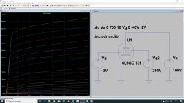
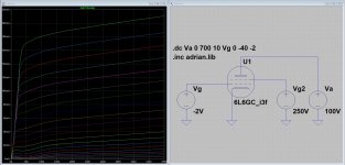
After that I still get results that resemble the GE plate curves (Va = 300V, Vg2 = 250V, Ia = 190mA instead of 200mA).
I'm running LTspice XVII(x64) Dec 3 2019 on Windows 10.
I also have the error
Code:
WARNING: bad call of user defined function in: "pow(pow([x+]1f,-n)+pow(y+1f,-n),-1/n)"I'm running LTspice XVII(x64) Dec 3 2019 on Windows 10.
Attachments
Rongon, would you do a test for me? Would you deceive x and y in my smin-function and tell me what happens?
I'd be happy to. How should I do that?
I'm using the older LTspice IV on Windows 10.
Would it help if I upload the .asc file?
FWIW, it's a push-pull amp using cathode bias of the 6L6s.
--
Last edited:
- open the code file with LTspice...How should I do that?
- copy the line which starts with „.func smin“
- insert the copy right below the mentioned line
- knock out the origin line with a * at its beginning, just to keep the origin code
- now, you can play with the copied code line. Replace x by y, and y by x.
- store the file
- run your simulation and tell me what happens
I‘m glad you do that, because I can‘t reproduce the mentioned warning on my Mac.
Do you work with windows or MacOS?
Thanks in advance, Adrian
Just now getting to this.
Does this look like what you'd like to see for this test?
The smin(x,y,n) statement is unaltered.
The {pow(pow(x+1f, -n)+pow(y+1f, -n), -1/n)} section in the original has been altered to what is shown above in the CODE box.
I'm running LTspice IV in Windows.
--
I still get an error after running the simulation.
--
I also tried changing smin(x,y,n) to smin(y,x,n) and got a similar error.
Changing the order of when 'x' appears and when 'y' appears only changes the order of when they appear in the error message.
--
Attached is the .asc - Maybe there's something in there that is exposing this from the 6L6GC model. You may need to put your ECC81 model in place of the 12AT7 model I have in there.
--
Does this look like what you'd like to see for this test?
Code:
.func smin(x,y,n) {pow(pow(y+1f, -n)+pow(x+1f, -n), -1/n)} ;Min-function with smooth trans.The smin(x,y,n) statement is unaltered.
The {pow(pow(x+1f, -n)+pow(y+1f, -n), -1/n)} section in the original has been altered to what is shown above in the CODE box.
I'm running LTspice IV in Windows.
--
I still get an error after running the simulation.
Code:
WARNING: bad call of user defined function in: "pow(pow(y+1f,-n)+pow([x+]1f,-n),-1/n)"
WARNING: bad call of user defined function in: "pow(pow(y+1f,-n)+pow([x+]1f,-n),-1/n)"I also tried changing smin(x,y,n) to smin(y,x,n) and got a similar error.
Changing the order of when 'x' appears and when 'y' appears only changes the order of when they appear in the error message.
--
Attached is the .asc - Maybe there's something in there that is exposing this from the 6L6GC model. You may need to put your ECC81 model in place of the 12AT7 model I have in there.
--
Attachments
Last edited:
Just from an academic standpoint, I would love to see that model as well! What a neat tube!
I want to use a 6Z10 or 6T10 compactron tubes like a standard 555IC using this concept.
A kind of Schimitt trigger using suppressor to screen resistive coupling. Those tubes include a pentode with the suppressor tied to a pin in the base, used as FM detector, capable of doing the hysteretic part of the IC.
Attachments
Just now getting to this.
Does this look like what you'd like to see for this test?
Code:.func smin(x,y,n) {pow(pow(y+1f, -n)+pow(x+1f, -n), -1/n)} ;Min-function with smooth trans.
--
Hi rongon
thanks a lot for doing the test. Did you recognize that the this brackets [] stayed around x, though your changings? That means that the warning concerns either about the x (way ever...) or the first parameter listed in my function smin(x,y,n).
You mentioned also, that you changed the parameter order to (y, x, n), which a similar result. Does "similar" mean, that the brackets [] are then around y in the warning?
I will run your .asc file on Wednesday, that will hopefully help to understand what happens...
all the best, Adrian
Hi rongon,
I have breaking news regarding the warnings due to my smin-function!
When I run your simulation on my Mac, everything is ok.
After installing LTspice on my win10 Laptop (actually intended for my job only...) I can now reproduce the warnings. After some playing, I have now a clear diagnosis:
In self defined functions (.func), LTspice for win don't like any parameter called x! (while LTspice for Mac does not have this issue.)
Ironically, the LTspice help gives the following example:
Example: .func Pythag(x,y) {sqrt(x*x+y*y)}
So, the super fast quick fix is to replace the x by z or another letter.
I guess that's something for Mike Engelhardt, I will write him some lines in the hope that he will fix that problem. If not, I will release a new 6L6GC model version.
all the best,
Adrian
I have breaking news regarding the warnings due to my smin-function!
When I run your simulation on my Mac, everything is ok.
After installing LTspice on my win10 Laptop (actually intended for my job only...) I can now reproduce the warnings. After some playing, I have now a clear diagnosis:
In self defined functions (.func), LTspice for win don't like any parameter called x!
(while LTspice for Mac does not have this issue.)Ironically, the LTspice help gives the following example:
Example: .func Pythag(x,y) {sqrt(x*x+y*y)}
So, the super fast quick fix is to replace the x by z or another letter.
I guess that's something for Mike Engelhardt, I will write him some lines in the hope that he will fix that problem. If not, I will release a new 6L6GC model version.
all the best,
Adrian
That's crazy!
I guess the thing to do would be to change 'x' and 'y' to 'v' and 'w' (for instance).
I'll give that a try.
Thanks for putting in the work to find that bug.
--
Will this fix it in Win10?
Doing that in the subckt keeps the error message from appearing. But is LTspice just skipping the altered line, or is that actually working?
--
I guess the thing to do would be to change 'x' and 'y' to 'v' and 'w' (for instance).
I'll give that a try.
Thanks for putting in the work to find that bug.
--
Will this fix it in Win10?
Code:
.func smin(v,w,n) {pow(pow(v+1f,-n)+pow(w+1f,-n),-1/n)} ;Min-function with smooth trans. ;altered 11/1/2020Doing that in the subckt keeps the error message from appearing. But is LTspice just skipping the altered line, or is that actually working?
--
Last edited:
Hi rongon,That's crazy!
I guess the thing to do would be to change 'x' and 'y' to 'v' and 'w' (for instance).
I'll give that a try.
Thanks for putting in the work to find that bug.
--
Will this fix it in Win10?
Code:.func smin(v,w,n) {pow(pow(v+1f,-n)+pow(w+1f,-n),-1/n)} ;Min-function with smooth trans. ;altered 11/1/2020
Doing that in the subckt keeps the error message from appearing. But is LTspice just skipping the altered line, or is that actually working?
--
yes, your proposed code will work - but be aware that it is sufficient to rename the x only.
The y does not cause any problems/warnings.all the best, Adrian
LTSPICE for Mac
LTSPICE is available for Mac!! I found it on Analog Devices Website for download and it loaded onto my Mac mini. I can SPICE now.
LTspice | Design Center | Analog Devices
LTSPICE is available for Mac!! I found it on Analog Devices Website for download and it loaded onto my Mac mini. I can SPICE now.
LTspice | Design Center | Analog Devices
Hi Adrian,
I'm a LTspice user on Linux, but for fun I decided to try your 6L6GC_i3d model in Micro-Cap 12 running in wine on Linux. After fixing the ".params is not a subckt" error (changed the line to + params: ), I now get "Error: Duplicate definition for ( RAD*XS*IAD**.". Any ideas?
I'm a LTspice user on Linux, but for fun I decided to try your 6L6GC_i3d model in Micro-Cap 12 running in wine on Linux. After fixing the ".params is not a subckt" error (changed the line to + params: ), I now get "Error: Duplicate definition for ( RAD*XS*IAD**.". Any ideas?
Same result. Thanks anyway.Hi cogsncogs,
to be honest, I haven't any idea why this error occurs.
But what I can say: Please use the 6_6GC_i3f model, as this version delivers correct results in circuits with ungrounded 6L6GC cathode.
cheers, Adrian
- Home
- Amplifiers
- Tubes / Valves
- Vacuum Tube SPICE Models