MTP2P50E
Thank you for mentioning these mosfets, I didn´t know 500V P-channel devices existed!
I immediately bought 10pcs for 2 dollars each at ebay.
Erik,
Thanks for the link, will look deeper into this interesting solution, have lots of 6080 lying around.
Rod,
Great advice, ordered 10 samples through OnSemi immediately. As you say BJT is not the obvious choice.
Also got the spicemodel from OnSemi to make some initial sims before testing IRL.
Fuling,
Do you have any direct plans for the PMOS?
reVintage:
Constant current plateloads! So far I´ve used MJE350 in cascoded bipolar CCSs for input and driver stages up to 300V B+, I also have a bunch of DN2540 that can take 400V but I haven´t used them as they seem very intolerant against ESD (people destroys them all the time).
A 500V 2A 75W P-channel device is something I have wished for for years!
With these devices I´m looking froward to squeeze at least 450Vp-p out of an 12B4A stage with 500V B+ and fixed bias, excellent for my cathode follower projects!
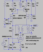
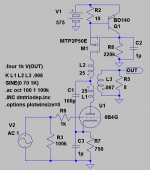
To make things more complicated a N-ch MOSFET could be added on the active side.
M1 makes a highZ CCS and M2 makes a LoZ Voltage source.
Could not find any highvoltage NMOS at OnSemi, any suggestions Rod?
R3 sets Iq, R2 sets balance in the current-mirror and R11 sets anode-voltage.
Must admit that "sand" is not my territory so I leave to someone else to adjust the circuit.
M1 makes a highZ CCS and M2 makes a LoZ Voltage source.
Could not find any highvoltage NMOS at OnSemi, any suggestions Rod?
R3 sets Iq, R2 sets balance in the current-mirror and R11 sets anode-voltage.
Must admit that "sand" is not my territory so I leave to someone else to adjust the circuit.
Attachments
hello Lars,
I like the 900V FQPF3N90 from Fairchild for all of this kind of work. The extra high voltage helps reliability! It's an isolated case TO-220, so building is easy.
Even so, some precautions using FETs in this kind of circuit:
- use 100nF or more on mains trafo secondary, else turn-OFF transients can wreck your FETs.
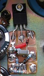
- use 330..1KOhm gate resistor as a stopper. Low inductance chip resistor is best (see pic). Power FET can give unwanted oscillation at 1..30MHz or more!
- With current source/mirror and cascodes in the same node as a triode, sometimes stoppers are not enough to stop oscillation. I have had success using Chip Ferrites (Murata BLM21A102S is very effective in this kind of position)
- 6V..10V zener (gate to source) to protect the oxide is vital! See the zener in the photo.
I like the 900V FQPF3N90 from Fairchild for all of this kind of work. The extra high voltage helps reliability! It's an isolated case TO-220, so building is easy.
Even so, some precautions using FETs in this kind of circuit:
- use 100nF or more on mains trafo secondary, else turn-OFF transients can wreck your FETs.
- use 330..1KOhm gate resistor as a stopper. Low inductance chip resistor is best (see pic). Power FET can give unwanted oscillation at 1..30MHz or more!
- With current source/mirror and cascodes in the same node as a triode, sometimes stoppers are not enough to stop oscillation. I have had success using Chip Ferrites (Murata BLM21A102S is very effective in this kind of position)
- 6V..10V zener (gate to source) to protect the oxide is vital! See the zener in the photo.
Attachments
High voltage current sources
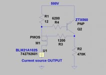
hello Fuling, I have had some good results using current sources in anode circuits. For current source applications using the P-channel 500V FETs, try using a chip resistor in the source circuit, and the PNP Zetex ZTX560 "cross-coupled" to form the current source.
When I built this circuit and compared to circuits with LEDs, zeners, opamps etc - it sounds MUCH better!
Put 1K in the P-ch gate, and about 6,2K in the PNP base circuit to compensate. Run about 1mA in the PNP, and increase the 6,2K if there is any oscillation.
for low power circuits, another choice for P-channel at 450V durability is the superb Zetex ZVP0545 -
http://www.zetex.com/3.0/3-3-2b.asp?rid=35
the capacitance is even lower than the ON part, so HF power supply rejection is improved still further, and makes a superb source.
"kenpeter: I simmed your (as usual weird circuit )and mating the 6V6 with the 2A3. Think you got something here. Have you actually tested it?"
As Ken mentioned in posts #92 and #94, one can get twice the power of SE using a P-P xfmr and still get SE sound using dissimilar Gm devices. Some previous threads on the subject:
http://www.diyaudio.com/forums/showthread.php?postid=1446107#post1446107
http://www.diyaudio.com/forums/showthread.php?postid=1597781#post1597781
http://www.diyaudio.com/forums/showthread.php?postid=638005#post638005
No reason to be using air gapped SE sfmrs anymore.
also regarding HV Mosfets:
There are some other HV P channel Mosfets besides the MTP2P50E which is somewhat dated, like FQP1P50:
500V, 63 Watt, Output capacitance only 40 pF. (the MTP2P50E has 100 pF output cap.) also the FQP3P50 85W 70 pF
For N channel there are FQP1N50,FQU1N80, FQP2N90 and STP2NK60, STP2NK90, 2SK3563, 2SK3566
Don
900V MOSFET
Hi,
I'm looking for a 900V (N-ch) MOSFET in a TO-3P or TO-247.
It should have relatively low charge, ideally the 2N90 or
3N90 but in a TO-3P. The deal is I'd like to actually use it
in a 700V circuit. What I could find is a 7BN90, which will
probably work OK but has a lot of capacitance. I worry
also that it's got a lot of small junctions in parallel and
could current-hog.
I'll try the ones I have but would like to have an alternative
in my back pocket in case these are less than ideal.
Thanks,
Michael
Attachments
As Ken mentioned in posts #92 and #94, one can get twice the power of SE using a P-P xfmr and still get SE sound using dissimilar Gm devices. Some previous threads on the subject:
Hi Don,
Didn´t you notice that we are already building a SE sound PP in:
http://www.diyaudio.com/forums/show...781#post1597781
Check post#26! Will soon report how it sounds. We will try two versions, 6B4G+6V6 and 6V6 triodestrapped+6V6.
This is another creature with 50% less current through the transformer.
Hello Rod,
Could you please publish a schematic with component values on your CCS! Didn´t understand your explanation
 .
.Hello,
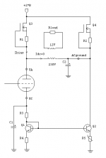
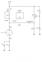
Can avoid using PNP and PMOS using something like this, since it seems they can be hard to find at reasonable effort.
This will also eliminate DC through the toroid totally! That is something to try at least.
No center tap needed.
Anode voltage is +B, the whole circuit will operate at +2*B. The right hand side of the primary is on AC gound. The signal swing at the primary is the same as in normal SE.
I'm pretty sure this is not new idea either, but tempting. No further compensation needed!
- Elias
Attachments
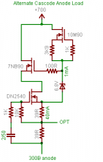
hello Lars, here's a quick schematic.
Running from 500V, the 12 Ohm sets the current (12 x 50mA ~ 600mV, the base-emitter voltage).
The 6200 Ohm base resistor is adjusted to keep things stable - but be sure to make very short connexions to the base and the FET gate (<20mm for preferance).
U1 is a Ferrite bead discussed above, to keep the impedance high all the way into the GHz range, and reduce further any tendancy to oscilllate. These chip ferrites must be mounted on some board - they break if wire is used!
Lots of FETs at Farnell, if that works OK with you, they offer quick free delivery, and card purchase if you spend something like 40 euro. Set up an account and there's no minimum purchase, and no delivery cost! Hej, look! they have even got a Sweden site:
http://se.farnell.com/1095086/semic...hild-semiconductor-fqpf3n80c&_requestid=89927
or UK
http://uk.farnell.com/1095086/semic...uct.us0?sku=fairchild-semiconductor-fqpf3n80c
Attachments
Hello,
After drinking more coffee this morning I realised the capacitor in my last schema is a bad idea. This is a sort of active parafeed. Need to think about temperature and tracking stabilisation more though. However idea is to feed zero DC current through toroid.
- Elias
After drinking more coffee this morning I realised the capacitor in my last schema is a bad idea. This is a sort of active parafeed. Need to think about temperature and tracking stabilisation more though. However idea is to feed zero DC current through toroid.
- Elias
Attachments
Elias:
I have seen that topology before, but in an active device mode:
http://www.diyaudio.com/forums/showthread.php?postid=638009#post638009
I'm also working on one with a 2-tube push-pull on the bottom.
I think you would need a DC servo across the bottom 2 elements if
you want to perfectly balance DC all the time (probably a good idea
with a toroid) so you can apply Ken's Brute Force or something like
that.
I guess you're going passive DC to avoid having sand in the sound
path. Seems similar to shunt regulation in a way.
Michael
Hello,
Revintage:
Signal current going through C1, so in a way it has the same characteristics as parafeed except it is not")
Michael:
Yes I remember that topology, but as I understand Smoking-amp circuit it has high impedance at both side of the primary. I was approaching AC ground on the other side. DC tracking is a must in these kind of compensation methods, I agree.
- Elias
Revintage:
Signal current going through C1, so in a way it has the same characteristics as parafeed except it is not
Michael:
Yes I remember that topology, but as I understand Smoking-amp circuit it has high impedance at both side of the primary. I was approaching AC ground on the other side. DC tracking is a must in these kind of compensation methods, I agree.
- Elias
Hej Elias,
The cap has the same function as what you called "supply cap" in your post #82. In other words you could as well connect it from the CT to ground and have a separate decoupling cap at 6B4Gs cathode.
The definition of parafeed is probably not what one should use here even if current is fed thorough a cap, as we among other things have DC through the windings.
One could also ground the CT to get rid of the cap and feed the circuit with +/- 290V.
Post#82 was purely SE, this is an asymmetrical PP variation where the now active MOSFET takes its input signal from ground.
It is funny how many ways there are to do this current compensation. Have you built your prototype yet? Our first version will hopefully play tonight or tomorrow .
.
The cap has the same function as what you called "supply cap" in your post #82. In other words you could as well connect it from the CT to ground and have a separate decoupling cap at 6B4Gs cathode.
The definition of parafeed is probably not what one should use here even if current is fed thorough a cap, as we among other things have DC through the windings
. One could also ground the CT to get rid of the cap and feed the circuit with +/- 290V.
Post#82 was purely SE, this is an asymmetrical PP variation where the now active MOSFET takes its input signal from ground.
It is funny how many ways there are to do this current compensation. Have you built your prototype yet? Our first version will hopefully play tonight or tomorrow
.Hello,
Revintage:
Reply to post no 115, that circuit looks good. I can see some similarities to this old patent
from this thread
http://www.diyaudio.com/forums/showthread.php?s=&threadid=52175&highlight=
The fact that you added current source at the top makes it really work!
Yes the currents are identical, but will it be the case for the windings? If not there is left over saturation that does not compensate. Well, maybe not a severe issue.
Signal goes through C1 but surely the tube will distort much more than that
- Elias
P.S. another prototype is on the way
- Home
- Amplifiers
- Tubes / Valves
- Using mains transformer as output transformer