Hi guys!
The amp is still playing fine.
The catodes are tied together with 30uf oil capasitor.
Soundstage and separation betwen instuments and vocals are wery good.
The system is dead silent at max volume on my pre.
I now playing the amp on my multicell horn/Beyma cp16 supertweeter.
Aleph 5 driving onken.
Revintage will help me on some mesurments this week.
Im curius on the distortion figures
Don,
Thanks for your insights. Putting it all together, it seems that the
current mirror is a current doubler for the triode that tracks changes
in average current with signal level at the time constant of 2X cathode
impedance and the not-so-big-after-all cap.
Lars,
Awaiting your measurements but cheers that you're happy with
the sound!
Michael
His cap can be half as large, because the series impedance of
two soft follower Cathodes is twice as much as a single soft
soft follower to GND (or hard GND follower).
Remember at the time I computed the large cap, the Triode
in question was mirrored x101 on that side alone. And the
Anti-side was even lower in impedance by a wide overkill.
Think I had specified an IGBT with well over 3 Mho's of Gm.
------------------------------------------------------------------------
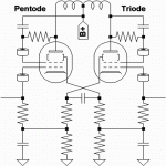
In regard to matched Pentodes, with one strapped for Triode.
The more I dream the most likely shape of this transfer curve,
the better I think it exactly right for an output stage. A wide
linear middleground with nicely rounded ends. With each end
rounded a bit differently to insure a good 2nd order masking
right before odd orders compress toward the final clip.
The curve might bear some resemblance to the transfer curve
of Superdriven SET in A1A2? Even though no actual A2 is ever
touched. I'm just picking a familiar curve for comparison of the
final shape seen by the load, not stating how it might or might
not be driven...
Might want to ref pentode screen to the anti-end of the OPT
though a low pass filter, rather than to B+. Prevents an error
in long time constant flux balance.
About the capvalue it is choosen at the point where the lowend is extended as much as possible. Lower you get a resonant "hump" and if higher value the -3dB is a a bit up. So to be able to use a film/oil cap the smallest possible cap is used. In SETORS case 33uF was close to optimal.
Also there is a SETOR-II proto on its way. I have found a way of lowering the distortion by almost 30% at 5W. Still the same nice SE distortion-spectra .
.
I have unwound two Talema trannys this weekend to get optimum load (3k a-a for parallelled 6B4G against a 6550). Not as hard as I thought as the two secondaries are wound pair-wise. To unwind the 12Vs for my SEPTOR only 14 turns had to be eliminated.
About the ripple, discussed in my ESLDD-thread, the problem is also solved in an easy way. The question is only how low ripple is needed at the output to be acceptable? I calculated my figures rel. to 1W,8ohm, 2,83V.
Also there is a SETOR-II proto on its way. I have found a way of lowering the distortion by almost 30% at 5W. Still the same nice SE distortion-spectra
I have unwound two Talema trannys this weekend to get optimum load (3k a-a for parallelled 6B4G against a 6550). Not as hard as I thought as the two secondaries are wound pair-wise. To unwind the 12Vs for my SEPTOR only 14 turns had to be eliminated.
About the ripple, discussed in my ESLDD-thread, the problem is also solved in an easy way. The question is only how low ripple is needed at the output to be acceptable? I calculated my figures rel. to 1W,8ohm, 2,83V.
"Also there is a SETOR-II proto on its way. I have found a way of lowering the distortion by almost 30% at 5W. "
Using some paralled triodes for the triode side will certainly lower distortion by lightening the loading.
If the secondary winding is in two sections, one could use half on each side (triode and "anti triode") as CFB windings. Makes it difficult to connect them together for speaker output though. I guess one could just put the whole CFB (or secondary) winding on one of the device's cathode circuit (ie, in series with cathode, usual CFB). Problem solved then.
Don
Michael Koster said:I have a pair of 414s, I'm thinking about baby Onkens and 511
horns. What drivers do you use?
Karlson K15 cabinet, at the moment loaded with Eminence Delta
Pro 12", and a crummy piezo on top with 20R in series.
I have parts except wood to build new Karlsons 18's in a taller
Koupler of the same width and depth. Eminence SigmaPro 18's,
Selenium D250X (narrow throw mid-horn (HL14?) to bounce off
dustcap of the 18's or flyswatter between) , Selenium D210Ti's
with P-Audio PH230 cheekhorns. No crossovers yet, I'm looking
at the Behringer with time delays and all the other whistles...
Amps I got class D's stacked in every corner... To be replaced
with Tubes as soon as possible.
Its a well known in parafeed amps that the output can be tuned by the choice of parafeed cap. Since parafeed output transformers have fairly high primary inductance caps in the region of between 2-4uf will usually produce a bass boost at about 10hz. So we are experiencing a resonant tank between the output transformers primary inductance and the parafeed cap.
In the case of a cathode bypass the same principles apply, but with a mains toroidal the primary inductance is lower so the cap value is higher to produce the same resonance.
I personally don't use it because the methods of feedback I employ reduces the low end roll off to below audble range.
Shoog
In the case of a cathode bypass the same principles apply, but with a mains toroidal the primary inductance is lower so the cap value is higher to produce the same resonance.
I personally don't use it because the methods of feedback I employ reduces the low end roll off to below audble range.
Shoog
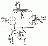
Seems to me that we could simplify the CCS/Mirror arrangement to get rid of the capacitor(s) in the signal path. Just connect the triode and "anti triode" cathodes together with a CCS tail to B-.
Then use a high value resistor divider and cap filter from the tail voltage to control the gate voltage of the CCS Mosfet, for a DC/envelope tracking CCS current level. (ie, tries to keep the DC tail voltage constant) Now put Gm(t)/Gm(a-t) of the input signal drive on the "anti-triode" grid/gate so that the tail voltage stays nominally constant AC signal wise. Still would have a LF response due to the RC, but would only be affected by the signal envelope and (ie the product of) triode non-linearity now.
Putting in additional CFB feedback would require putting most of the CFB winding on the triode's cathode (determined by the ratio of the device gm's again) to maintain a steady tail voltage. Adjust the CFB tap going to the CCS for zero AC signal there after taking into account the anti-triode source/cathode AC drive.
Or, put all the CFB winding in the triode's cathode side and either dispense with the "anti-triode" drive or tune it for a complete null at the tail.
Don
"could you draw it?"
No problemo. Seems an obvious solution to me, someone may have already mentioned something similar. I think Anatloyi (Wavebourn) mentioned such a self regulating CCS for something.
The two drive signals are scaled so that the tail voltage AC variation is nulled to a minimum.
No problemo. Seems an obvious solution to me, someone may have already mentioned something similar. I think Anatloyi (Wavebourn) mentioned such a self regulating CCS for something.
The two drive signals are scaled so that the tail voltage AC variation is nulled to a minimum.
Attachments
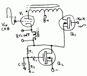
CFB version. The drive signals can be adjusted for a minimum AC null on the tail again. Or maybe just leave Q1 with a steady bias on its gate, could be good enough. Just trying to keep audio out of the CCS tail's slow regulation (no resonance then). The slow regulation is for compensating non-linearity in the tube, causing growth of current on large signal bursts.
Since the audio doesn't go thru the cap, the RC low pass can be set to be lower than the L (OT primary) and C resonance, avoiding resonant activation by enveloping, I think.
Since the audio doesn't go thru the cap, the RC low pass can be set to be lower than the L (OT primary) and C resonance, avoiding resonant activation by enveloping, I think.
Attachments
And now for something completely different:
Anyone remember what engineer this this crossed
bias balance was named for? I've seen it mentioned
here before, recently too, I'm sure of it... But I draw
a blank what name to search for...
Maybe those bypass caps at the bottom should have
been moved up and used as coupling caps from grid
stoppers to the driver(s) instead... My bad.
Attachments
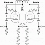
Serious bypass goofup fixed...
As for a resonance? I suppose it probably has one...
I don't see any reason it would be within the audio
passband. Does it cause DC balance to oscillate?
Would that mode ever have a gain approaching 1?
Are you suggesting its a motorboat of some sort?
As for a resonance? I suppose it probably has one...
I don't see any reason it would be within the audio
passband. Does it cause DC balance to oscillate?
Would that mode ever have a gain approaching 1?
Are you suggesting its a motorboat of some sort?
Attachments
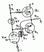
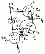
How about just getting rid of the transformer altogether. More problems than its worth. Now we get a SET emulation without triode or transformer. Probably works better than SET. Q2 would be a constant Beta part. Uses complementary current outputs. Maybe needs some extra resistance in the Q1 source lead.
Attachments
Fixed
On the Blumlein scheme, I wouldn't think it would be any more problem than parafeed. Just have to be careful where the resonance falls so it doesn't get excited. Can probably make it a damped resonance as well. But if it can be gotten rid of ..... one less artifact.
On the Blumlein scheme, I wouldn't think it would be any more problem than parafeed. Just have to be careful where the resonance falls so it doesn't get excited. Can probably make it a damped resonance as well. But if it can be gotten rid of ..... one less artifact.
Attachments
- Home
- Amplifiers
- Tubes / Valves
- Using mains transformer as output transformer
