Hello and Good evening! 
Congratulations of working proto! (even only one channel)
If the problem is core saturation, this thread is the right place to get that solved!
- Elias
hoktuna said:Goooooodmorning amerika
One channel of "the prototype"is upp and playing sweeeet music.
The other channel need some tweeking,it is distorted(right word?)
Maybe core satur,we´l se tomorrow.
Congratulations of working proto! (even only one channel)
If the problem is core saturation, this thread is the right place to get that solved!
- Elias
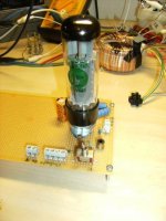
This is the proto hoktuna built, but with 6P3S instead of 6V6. We discussed over the phone and came to the conclusion that the second channel probably had a faulty 6P3S or a leaking coupling cap. If not so, it could also be a self-oscillating 6C45.
We are looking forward to both channels working, to evaluate the amp soundwise.
An externally hosted image should be here but it was not working when we last tested it.
We are looking forward to both channels working, to evaluate the amp soundwise.
Next thing will be too hook the amp on my main speakers.
Onken 360L whith Altec 416 8A
Homebrewed Altec multiell with JBL 2441.http://i194.photobucket.com/albums/z134/hoktuna/DSC04462.jpg
Onken 360L whith Altec 416 8A
Homebrewed Altec multiell with JBL 2441.http://i194.photobucket.com/albums/z134/hoktuna/DSC04462.jpg
Here is the amp with ps.
http://i194.photobucket.com/albums/z134/hoktuna/DSC07103.jpg
http://i194.photobucket.com/albums/z134/hoktuna/DSC07103.jpg
Congratulations Hoktuna and Lars!
You have a working push-pull signal-mirrored amplifier.
The bypassed current mirror may be a very good solution to DC
balance and AC drive. I look forward to some measurements.
It looks like you're working into about 11K anode-anode based
on the transformer ratio. What's your output at OPT saturation?
Also, a great use of a pentode, pushing current around under the
control of a DHT.
I have a pair of 414s, I'm thinking about baby Onkens and 511
horns. What drivers do you use?
Cheers,
Michael
Actually the impedance ratio is 9000:8.
One must measure the unloaded secondary to determine voltage ratio and for this Autema 30VA it is 230:6,8V.
A 230:9V unwound to 8,4V unloaded would be perfect......
Anyway we will soon measure and listen more.
Michael,
I used 414 Onkens earlier together with 511/802s and 077. Now the 511 are being rebuilt to take a 2" driver.
http://www.revintage.se/narbak.JPG
http://www.revintage.se/frontred.JPG
Hoktunas DIY-multicells with 2441(!) and Onken 416
http://img385.imageshack.us/img385/435/multicellfr8.jpg
That tower looks like an open baffle. If you have
experience with 414s in OBs I'd be very interested
indeed, because I have a Heil AMT I'd like to pair up
with a dipole mid. Conventional wisdom is the 414s
too low Qt for OB but what if I use it as a mid down
to 100-120 Hz and make my sub go up to that?
Also that octagon tube looks like an interesting sub.
I'm also working on a tube sub design.
I guess there is speaker design forum...
Can't wait to hear more about the SETOR.
Cheers,
Michael
Hi Revintage,
C1 between the cathodes of 100mFd does that take the place of the 470mFd from the triode cathode to deck?
Still trying to work out the filament supplies with directly heated tubes and then to apply the CCSs.
I will use a modded PC supply for one tube, has anyone used 12V SS lamp psus for tube filaments?
Cheers
Mike.
C1 between the cathodes of 100mFd does that take the place of the 470mFd from the triode cathode to deck?
Yes, actually even a smaller value like 33u will be adequate.
Thanks for the reply,
I reckon I will start with a common supply for the filaments, ie cathodes tied together (Directly heated Cathodes) and put a CCS between the Filament supply and deck. As for drive it will be a triode strapped EL34 and Tubelabs driver setup. Got lots to try out here, anyway the sheet of 10mm Teflon has arrived to make the base for the triode,so I went out to get a hole cutter this morning. Still need to find some brass sq section to make the heater connectors.
Got hold of some iron to rewind for HT will start with 500V and doubler or straight for the first tests ie 650/700V. With my O/P transformer will be happy with 25/30W. Once It sort of works then I can decide what direction to take.
Thanks again
Mike.
By the way did your amp(Hokunas)? work with the cathodes tied together, I 'm sure that you will have tried this?
Tying cathodes together...
While that "works", doesn't work unless non-identical
tubes have some other servo to match up the idle DC.
Splitting the current source into parallel halves is the
simple brute force way to accomplish that. Joining the
cathodes here would defeat the DC balance.
If you are just gonna use identical Triodes, thats plain
ordinary balanced differential. Won't behave as single
ended. Wether they are cap bridged over two current
sources, or hard wired together over one. If the GMs
are too closely matched, they blend into a push-pull
amplifier. And cancel out any single ended character.
The Pentode (or MOSFET) "Anti-Triode" is a cascode
slave that passes the master Triode's cathode current
back up the other end of the Push-Pull OPT without
adding any new flavors of its own. The Triode abuses
that cascode path for its cathode bypass. It appears
to Triode as-if hard bypassed to a faithful ground of
very low impedance.
Devices chosen for each pathway must be very different
to insure that only one gains control over the behavior.
And the master here will always be the weaker device.
The Triode must have significantly less current gain than
the Pentode or MOSFET if blending is to be avoided.
Hard current sources below, insure that no current
variations of the Triode can escape, except by way
of the Cascode/Anti-Triode path. Nor any imbalance
of DC. No simple way to tie directly heated filaments
together with this topology. I am open to suggestions
if you know some sneaky trick that makes this possible.
I was just looking into GE's 6L6GC spec sheet to see how much
different Gm might be for Triode and Pentode at the same point?
I figured with Mu factor "Screened" out of the picture, Pentode
would have the higher current gain. Yet it seems I was wrong...
Picking a handy point that was easy to read on both charts...
250V for both Plate and Screen. Also choosing -15V for G1.
Here at least, the sum of all Pentode currents seem to agree
with the Triode figure. There are other G1 points on 250+250
Pentode where they do not. I don't yet understand why with
plate and screen both equal, the pentode should ever NOT
agree with the triode model. Go figure...
Anyways, interpolating Gm from the nearest published curves:
6L6GC as a Pentode: -15V G1 (+/- 1V)
250V Plate @ 65.5mA
250V Screen @ 4.5mA (70mA total), Gm = 6mA/V
6L6GC as a Triode: -15V G1 (+/- 5V)
250V Plate & Screen @ 70mA total, Gm = 6mA/V
Exactly the same... Intrisic Mu does not seem to reduce Gm???
Certainly not the result I was expecting to discover.
I guess this would make a poor Triode/Anti-triode if the purity of
single-ended triodeness was the sole figure of merit. I am not
saying it would sound bad, only thats its a whole nother animal.
Some result like: ((Triode+AntiPentode)-(Pentode+AntiTriode))/2 ?
A blended result...
Lars had already made an observation that 2A3 + 6V6 might be
more of an unbalanced differential than pure Triode-AntiTriode...
Hoktuna's build (looks like 6L6 to me) is reported to sound very
good.
If we stiffen the Pentode side's Gm by adding a FET under it,
then it hardly matters anymore if that side's 6L6 is strapped
as Pentode, Triode, or UL. Simplest to leave it as Triode, and
not worry how screen currents muck with the balance of flux.
Good argument to just leave the anti-triode side pure sand...
MJK's pure FET anti-triode is also reported to sound very good.
Mind you I havn't cross-checked this odd result against other
popular power pentodes. And may be that I have interpolated
the Gm incorrectly. And who is to say if a perfect or imperfect
anti-triode mode sounds better? I simply do not know...
Ken,
gm = u/rp if I recall correctly
u is high and rp is high with the pentode. I thought it's
the high rp that isolates the intrinsic feedback and makes
the pentode a slave to the triode.
Having said that, I'm on the verge of implementing a
MOSFET-tube cascode and I suppose triode will work
as well. There are dozens of cheap TV sweep tubes
and even vertical amp triodes that will do the job.
I'm looking at EL86s at the moment. My only issue
with it is the separate floating heater supply for each
one in the SRPP-like totem pole mirror configuration.
SETOR --
Also thinking about the cathode drive of the SETOR.
Is it the case that the pentode signal current is always
the inverse of the triode signal current through the
AC coupled current mirror? I'm having trouble understanding
how the AC current works...
For triodes, yes.Michael Koster said:gm = u/rp if I recall correctly
Pentode's don't have "Mu" for reason you just explained.Michael Koster said:u is high and rp is high with the pentode. I thought it's
the high rp that isolates the intrinsic feedback and makes
the pentode a slave to the triode.
[/B]
Ignoring the plate is essential, but what happens at the
node shared by the two cathodes if Gm is equal, yet not
quite exactly the same distorted curve?
A slave to what signal? You already said it can't be the
plate, therefore what happens at the cathode is very
important in terms of what both tubes might do!
I suspect: The triode then becomes halfway anti-pentode.
And the "whatever it is now" an anti-undefined mess...
I'm not saying its a mess that sounds bad, it might sound
just fine, maybe even great. Saying only that it is a blended
curve of Triode and Anti-Pentode on the one side, Pentode
and Anti-Triode on the other... If Gm's are too equal.
Consider from the perspective of "the tail wags the dog."
What happens at the Triode if you drive from the Pentode
end? I have reason to believe the 2nd order is cancelled,
and the blended curve is fairly linear. With any remaining
non-linearities to some extent, converted to odd orders.
There is no difference but inversion which end is driven.
I take that back about the blended curve being linear...
As GM's do become unequal the moment either tube's
operating points swing off center. The blended curve
will slave to whichever end at that moment happens
to be in deeper cutoff...
The blend is not the absolute difference of curvatures,
but rather a baton of control passed gently back and
forth. Half a curve, half an anti-curve, Frankensteined
together at smooth well healed seams.
This is true even for balanced differential stages. You
are seeing mostly half a face at the extreme outside
edges of the half silvered mirror. You are only fooled
because the other half looks just like it. -Err what???-
Its too early for mushroom tea.
"Undefined" was perhaps closer to the truth. That is
no argument one shouldn't built it. Might even be an
argument for it. Sometimes surprises are good.
That all makes for interesting reading and from this it appears that I have an unfortunate choice of tubes with the triode maybe having a slightly higher gm.
As for setting Ia to be equal, I don't see that as any sort of problem. On the pentode half I assume that the UL tap on the OPT would also be used. Suck it and see !
Mike.
As for setting Ia to be equal, I don't see that as any sort of problem. On the pentode half I assume that the UL tap on the OPT would also be used. Suck it and see !
Mike.
The pentode does actually have a Mu just like triodes, its just very high. One can smoothly transition between pentode and triode with the formula: Mu = gm1/(%UL*gms +gmp) Curve-wise, the pentode curves have a virtual triode shaped extension into the - plate voltage region, but screen current eats them up as Vp drops below Vs, causing the knees.
For the SETOR with AC coupled current mirror, it looks just like a single current source at the "anti" cathode still, except at very low frequency. So the triode and "anti-triode" AC currents must sum to constant current still for audio.
On the gm ratio between the devices:
Having the plate rp high is helpful because it has an inverted signal on it with respect to the driven cathode (or source) and so that effectively maintains the high gm looking into it's cathode. For the triode side to behave as a pure triode, it needs its cathode pinned to gnd (AC). A high gm on the "anti" side effectively does this.
With both sides having equal gm (for a pentode and triode combo) we would have to take into account the triode's plate swing. Subtracting some Vp(ac)/Rp out effectively from its g1 gm to compare with the pentode side g1 gm. ie like Miller effect. So using identical pentodes, with triode strapping on one of them, would leave the pentode with a little higher gm effectively.
Driving on the high gm "anti" side (grid or gate) should work just as well as driving on the triode side grid, since it just creates a voltage difference on the triode side between grid and cathode too. Could use drive to both sides, but the drive signals may sound like nornal P-P themselves unless some precautions are taken in the preceding stage/splitter for accuracy.
Don
- Home
- Amplifiers
- Tubes / Valves
- Using mains transformer as output transformer