Got sooooooo excited of the idea . Then I remember I saw some Italian guy, Ciuffoli(?), having used the other half of a PP OPT for SE current compensation with another tube.
Anyway, I did a sim just to check out that it basically would work.
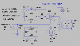
In this example I used 2A3/6B4G(can also be a triodemode EL34)as active tube and a 6V6 in tetrode mode instead of CCS. According to the data sheets 6V6 has a Rp of 80kohm and it need no heatsinks as a sand-CCS would! Also used two LM317, at 50mA, as current sinks. Think Shoog used them in his 6080PP.
A 50VA 115+115:6+6 (6,8V unloaded) toroid, has a primary inductance of ca 100H which means 25H/side. This is enough for the 2A3. Load will be 2,3kohms.
Not very efficient but I am sure it will have a SE signature.
Is there someone who has already tried this variation on the theme?
. Then I remember I saw some Italian guy, Ciuffoli(?), having used the other half of a PP OPT for SE current compensation with another tube.Anyway, I did a sim just to check out that it basically would work.
In this example I used 2A3/6B4G(can also be a triodemode EL34)as active tube and a 6V6 in tetrode mode instead of CCS. According to the data sheets 6V6 has a Rp of 80kohm and it need no heatsinks as a sand-CCS would! Also used two LM317, at 50mA, as current sinks. Think Shoog used them in his 6080PP.
A 50VA 115+115:6+6 (6,8V unloaded) toroid, has a primary inductance of ca 100H which means 25H/side. This is enough for the 2A3. Load will be 2,3kohms.
Not very efficient but I am sure it will have a SE signature.
Is there someone who has already tried this variation on the theme?
Attachments
Forgive me if I'm wrong, but I think you are possibly going to achieve the worst of all possible worlds. The bad distortion of PP and the poor control of SE.
As I said before, SE seems like a real waste of time with toroids. I can attest to the fact that a well implemented PP has very few faults and the toroidal transformer gives the PP a chance to shine.
This is because for the same reason that a toroidal core saturates very easily, it also has extremely low hysteresis. This is one of the main advantages that traditional SE transformers have over PP transformer's - but SE transformers have their own nasties in the form of leakage inductance. The toroidal has neither leakage inductance or hysteresis. It is almost by definition the best output transformer possible. The only issue to watch out for is ringing produced by interwinding capacitance.
Just build a PP amp. Consider trying a self splitting arrangement for phase splitting. This is almost exactly what you are proposing, but with the same valves on the output. The main distortion component will be 2nd harmonic which by coincidence is what you will get from SE.
Br Cornelius
Hi Shoog,
You must explain how the "bad distorsion of PP" will occur in.
About "poor control of SE" I can agree in general but it must depend on the loudspeaker used.
I can clearly see the virtues of toroid and PP but for some applications SE really shines. I was thinking of maybe trying it later for my horn-mids from 300Hz and up. But only if my PP 6B4G fails to deliver.
If I where to build a fullregister toroid PP I would go fully balanced without caps and with iron between driver and output. Didn´t you do something like that with your 6080PP?
You must explain how the "bad distorsion of PP" will occur in.
About "poor control of SE" I can agree in general but it must depend on the loudspeaker used.
I can clearly see the virtues of toroid and PP but for some applications SE really shines. I was thinking of maybe trying it later for my horn-mids from 300Hz and up. But only if my PP 6B4G fails to deliver
.If I where to build a fullregister toroid PP I would go fully balanced without caps and with iron between driver and output. Didn´t you do something like that with your 6080PP?
My 6080PP had an SE front end feeding a toroidal as an interstage phase splitter and then into a differential pair output stage. This is the only application in which the toroidal has let me down in that the interwinding capacitance was to high. This would not have been a problem if I had been able to step down at the same time.
I got my SE flavour from the front end.
I would say, go ahead and build it, but be prepared to change it to a self splitting PP pair. Unfortunately in all my builds I have had to use cathode bypass on the finals in order to implement the cathode CCS.
Shoog
I got my SE flavour from the front end.
I would say, go ahead and build it, but be prepared to change it to a self splitting PP pair. Unfortunately in all my builds I have had to use cathode bypass on the finals in order to implement the cathode CCS.
Shoog
Hello,
For cathode bias current adjustment easiest way would be a meter in the front panel and a tuning knob beside it. For a PP can use additional zero-crossing meter to adjust the exact balance. Tuning can be done with no trouble, I think. No fancy electronics needed. Quite boring actually
Shoog said:
Not very elegant at all.
This is the main reason I started using cathode CCS to save constant adjustment. I feel certain that this compromises the sound a little, but I really do not want to be fiddling all the time and am willing to pay the price.
For cathode bias current adjustment easiest way would be a meter in the front panel and a tuning knob beside it. For a PP can use additional zero-crossing meter to adjust the exact balance. Tuning can be done with no trouble, I think. No fancy electronics needed. Quite boring actually
Hello,
Can you explain how a PP is having main distortion 2nd order?
As I understand it, even order distortion components have same sign in both of primary windings of a PP transformer, and because the transformer calculates the difference of primary windings they cancel at the secondary. What is left at the output will be only odd order distortion (and signal of course). In practise symmetry is not ideal so some even order will get through, but how it can be dominating distortion is beyond me.
- Elias
Shoog said:
Just build a PP amp. Consider trying a self splitting arrangement for phase splitting. This is almost exactly what you are proposing, but with the same valves on the output. The main distortion component will be 2nd harmonic which by coincidence is what you will get from SE.
Can you explain how a PP is having main distortion 2nd order?
As I understand it, even order distortion components have same sign in both of primary windings of a PP transformer, and because the transformer calculates the difference of primary windings they cancel at the secondary. What is left at the output will be only odd order distortion (and signal of course). In practise symmetry is not ideal so some even order will get through, but how it can be dominating distortion is beyond me.
- Elias
Can you explain how a PP is having main distortion 2nd order?
Use a common cathode input stage running at low current with a high value load . I find with this technique that 2nd order dominates
cheers
316A
Hello,
Ok, distortive input stage. I was thinking about output stage, but I suppose it doesn't matter where the distortion is coming from. Have to keep an eye on odd order distortion generated by the PP output stage though.
- Elias
316a said:
Use a common cathode input stage running at low current with a high value load . I find with this technique that 2nd order dominates
Ok, distortive input stage. I was thinking about output stage, but I suppose it doesn't matter where the distortion is coming from. Have to keep an eye on odd order distortion generated by the PP output stage though.
- Elias
Use a common cathode input stage running at low current with a high value load . I find with this technique that 2nd order dominates
Hi 316a,
You might be right but I thought we where discussing transformer-coupled output stages here?
Did a sim on Shoogs suggestion about selfsplit. The distortion lowered drasticly in the sefsplit but the spectrum was higher from 3rd and downwards with the uneven higher than the even. The SE had a gradually falling spectrum. A selfsplit also needs almost the double drive voltage.
We are building a prototype this weekend. See the last schematic in this Swedish thread:
http://www.hififorum.nu/forum/topic.asp?TOPIC_ID=70440
Did a sim on Shoogs suggestion about selfsplit. The distortion lowered drasticly in the sefsplit but the spectrum was higher from 3rd and downwards with the uneven higher than the even. The SE had a gradually falling spectrum. A selfsplit also needs almost the double drive voltage.
This surprises me a little because people who have built amps on this principle describe them as SE sounding.
The way I would implement it (and will when I get around to building my own), is cathode CCS in each leg. 1000uf bypass caps from the cathode. Tie the caps negative legs together and ground this node through a 300R resistor.
This is a differential output stage with a earth path for the error signal. Allan Wright experimented with it and said it was the best setup he used short of individual bias adjustment and a shared CCS. This is the setup I use in all my amps. I originally used a 1meg resistor in place of the 300R, but found the lower value to sound smoother.
Shoog
Hi all,
seeing As i am very much on a tight budget and that I'm a bit lazy, an idea crossed my mind.
I've seen hybrid amps with Valve (tube) preamps and Solidstate O/P stages but never Solidstate drivers etc with Valve O/P stages.
If ordinary mains trannies are OK to connect your tranny amp to ESLs what can I say! At least with big bottles there is visual impact.
With an IC amp driver transformer coupled to a tube O/P stage, should be the best of both worlds.
Mike
Ok, distortive input stage. I was thinking about output stage, but I suppose it doesn't matter where the distortion is coming from. Have to keep an eye on odd order distortion generated by the PP output stage though.
For the output stage either dissimilar or poorly matched valves would generate plenty of 2nd
cheers
316A
Thought about the current adjustment and maybe you could use a Current Mirror? R7 fine adjusts bias.
An externally hosted image should be here but it was not working when we last tested it.
Hej Elias,
According to the data sheet it is 80kohms.
About the DN2540 CCS it is almost to be looked upon as an "industry standard" in diy-audio !
My friend Hoktuna have built a prototype with a 30VA that probably will be ready next weekend.
What is the output impedance of U1 anode?
According to the data sheet it is 80kohms.
About the DN2540 CCS it is almost to be looked upon as an "industry standard" in diy-audio
!My friend Hoktuna have built a prototype with a 30VA that probably will be ready next weekend.
Hello,
I think the linearity of output impedance of U1 is the key, not it's exact value. It will be mixed with the distortion of U2 and together they will define how is the distortion of the last stage. Ideally we would like to have output impedance be as linear as possible, so that distortion of U2 will deliver the SE sound we are after.
Well, M1 seems to be configured as source follower and thus has very low impedance, just the opposite we want from CCS. Why not to change it to P FET and connect drain directly to the anode of U5. Impedance will be much higher and can get rid of R10 also.
Hopefully your friend succeeds building the proto. I'll be looking forward for the results, preferably with some measurements
- Elias
revintage said:According to the data sheet it is 80kohms.
About the DN2540 CCS it is almost to be looked upon as an "industry standard" in diy-audio
My friend Hoktuna have built a prototype with a 30VA that probably will be ready next weekend.
I think the linearity of output impedance of U1 is the key, not it's exact value. It will be mixed with the distortion of U2 and together they will define how is the distortion of the last stage. Ideally we would like to have output impedance be as linear as possible, so that distortion of U2 will deliver the SE sound we are after.
Well, M1 seems to be configured as source follower and thus has very low impedance, just the opposite we want from CCS. Why not to change it to P FET and connect drain directly to the anode of U5. Impedance will be much higher and can get rid of R10 also.
Hopefully your friend succeeds building the proto. I'll be looking forward for the results, preferably with some measurements
- Elias
Hello,
I did some additional test with other mains transformers as well. If nothing else it can serve as a reference and a sort of proof for myself that going toroidal route is the best choice.
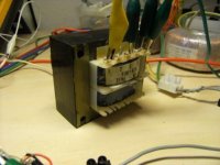
This is a 110V + 110V / 12V + 12V EI core transformer. Not sure about the VA rating but considering wire thickness I would say it's close to 100VA.
First of all with this transformer in my proto SE amp, f-3dB = 5kHz. Very poor! Also response at 20Hz is heavily distorted as well. Interestingly DC compensation didn't improve things nearly as much as for the toiroid. This one is abandoned!
I did some additional test with other mains transformers as well. If nothing else it can serve as a reference and a sort of proof for myself that going toroidal route is the best choice.
This is a 110V + 110V / 12V + 12V EI core transformer. Not sure about the VA rating but considering wire thickness I would say it's close to 100VA.
First of all with this transformer in my proto SE amp, f-3dB = 5kHz. Very poor! Also response at 20Hz is heavily distorted as well. Interestingly DC compensation didn't improve things nearly as much as for the toiroid. This one is abandoned!
Attachments
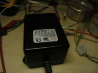
This is another EI core I tested in my proto SE amp. It's 230V / 12V 60VA transformer. As a side note, originally this one is intended for an indoor halogen light set.
I measured f-3dB bandwidth 60Hz...3.8kHz. No additional testing needed for this one!
Time to look at the toroids again
- Elias
I measured f-3dB bandwidth 60Hz...3.8kHz. No additional testing needed for this one!
Time to look at the toroids again
- Elias
Attachments
Hej Elias,
Think you are wrong here. The 10k is only there to prevent to much voltage over the Supertex. Here is some graphs showing impedance. Found this while googling, look for the "Supertex DN2540 single":
http://www.pacifier.com/~gpimm/ccs_performance_other.jpg
Well, M1 seems to be configured as source follower and thus has very low impedance, just the opposite we want from CCS. Why not to change it to P FET and connect drain directly to the anode of U5. Impedance will be much higher and can get rid of R10 also.
Think you are wrong here
. The 10k is only there to prevent to much voltage over the Supertex. Here is some graphs showing impedance. Found this while googling, look for the "Supertex DN2540 single": http://www.pacifier.com/~gpimm/ccs_performance_other.jpg
- Home
- Amplifiers
- Tubes / Valves
- Using mains transformer as output transformer