hello Elias,
I suspect the saturation of the core happens when you have dc current AND some low-frequency power going through the trafo. Maybe 50mA and 20W at 30Hz, or something like that.
I would test it like this: Take 2 of the trafos and wire them back to back (43V to 43V). Put one of the 230V primaries on the mains supply. Connect your current source through the 43V windings, and apply DOUBLE the current through them (to account for the dc flux going through both trafos). Connect a load to the opposite primary (the one furthest from the mains) use 2K Ohm (50W rated) for a 25W test.
 Take care with mains voltages! Now switch on and measure the mains waveform on the 43V winding, and vary the dc current to check for saturation.
This is a very interesting idea, and I would be interested to see the outcome!
I suspect the saturation of the core happens when you have dc current AND some low-frequency power going through the trafo. Maybe 50mA and 20W at 30Hz, or something like that.
I would test it like this: Take 2 of the trafos and wire them back to back (43V to 43V). Put one of the 230V primaries on the mains supply. Connect your current source through the 43V windings, and apply DOUBLE the current through them (to account for the dc flux going through both trafos). Connect a load to the opposite primary (the one furthest from the mains) use 2K Ohm (50W rated) for a 25W test.
Take care with mains voltages! Now switch on and measure the mains waveform on the 43V winding, and vary the dc current to check for saturation.This is a very interesting idea, and I would be interested to see the outcome!
Hello,
Rod:
I tested with 100mA in primary while 1W 20Hz-20kHz signal was driven to the load. In this test setup I see absolutely no saturation.
I know 1W AC is quite small power for a toroid like this. Maybe if I would use much more power I could see something. But then, my idea was to use toroid in SE with max power maybe 10W or less.
Regarding your suggestion, what would be the purpose of the other transformer? I can simple load the secondary of the first transformer and feed the DC as well. How would it be different case?
- Elias
Well, you have a box of them, so I guessed that 2 would be easy to find!
Having the load resistor on a remote winding, and the dc current through a different one means that the dc does not flow through the load resistor. This way, there will be no interaction between the current source and the load resistor - for easier measurement.
Having the load resistor on a remote winding, and the dc current through a different one means that the dc does not flow through the load resistor. This way, there will be no interaction between the current source and the load resistor - for easier measurement.
"I know 1W AC is quite small power for a toroid like this. Maybe if I would use much more power I could see something. But then, my idea was to use toroid in SE with max power maybe 10W or less."
1W is a small amount to transfer, but where the transformer
saturates on AC is basically as function of peak voltage and
frequency , i.e. v/f (according to a form of Faraday's law) if
we ignore DC for the moment.
The primary of the toroid is built for 115V and 60 Hz (assume)
You could drive the primary at 20 Hz with 1/3 the voltage or
about 38V RMS (to be safe). You might drive higher voltage at
higher frequency also by the same reasoning.
The amount of power transferred at saturation at 20Hz at 38
volts RMS depends on the load impedance reflected to the primary
and other losses. Your use of a 43 volt secondary with 8 ohms
will reflect about 55 ohms to the 115 volt primary. It only takes
7.5 volts into 55 ohms to produce one watt, far below the
saturation voltage of your primary. That probably explains why
the DC had little effect.
When you use the toroid in the anode circuit of a tube amp,
the signal voltage will be closer to saturation. If you use a 200
ohm load resistor, the primary may saturate around 1 watt. That
may give you a better idea of the interaction between DC and
signal and a closer approximation to the load presented to
a tube driving a speaker with your home-wound secondary.
Your signal generator may need to drive 38V RMS to saturate
one primary at 20 Hz.
Michael
Hello,
Well, according to this 'v/f' law I could put only zero volts at DC without saturating the core. I just fed 100mA DC without saturation.
The primary AC current in the test was 130mA to produce 1W load dissipation at secondary. It's the current that will saturate the core regardless of voltage since voltage is a byproduct depending on impedance levels.
So, if I'll keep the AC and DC currents within these limits the core does not saturate, it seems to be. I think I can even make them higher, but for that test I need more steem for my signal generator.
- Elias
Elias said:Hello,
Well, according to this 'v/f' law I could put only zero volts at DC without saturating the core. I just fed 100mA DC without saturation.
The primary AC current in the test was 130mA to produce 1W load dissipation at secondary. It's the current that will saturate the core regardless of voltage since voltage is a byproduct depending on impedance levels.
So, if I'll keep the AC and DC currents within these limits the core does not saturate, it seems to be. I think I can even make them higher, but for that test I need more steem for my signal generator.
- Elias
There is of course more to Faraday's law than v/f, and it
may be true that in a "perfect" inductor with zero flux
leakage etc., any DC at all will saturate the core.
Good thing real devices are imperfect then
You are on the right track with measurements. Keep an
open mind and observe.
Cheers,
Michael
Of course. My tube dynamic headphone amp was inspired by this,poynton said:Could you parafeed of a tube amplifier?
Andy
http://www.nutshellhifi.com/gary/index.html
but will not be the same in the detail of the design. I have some other OPTs that I will use, but a cliplead prototype worked well with mains OPTs in parafeed.
Hello,
I build a SE proto amplifier with EL34 and 115V+115V / 43V + 16V 105VA toroid. Nice weekend project by the way.
I achieved a breakthrough since I was able to make the core to saturate! But then I also was able to compensate the saturation.
Protoamp setup was like this:
EL34 in triod mode, B = 280V, Ianode = 55mA, toroid primaries in series, 8 ohm load at 16V secondary, DC compensation current at 43V secondary.
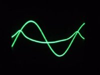
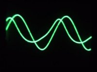
Without compensation response at 20Hz looks really horrible!
Power dissipation at the load about 0.5W.
In the pic there is input and output shown.
I build a SE proto amplifier with EL34 and 115V+115V / 43V + 16V 105VA toroid. Nice weekend project by the way.
I achieved a breakthrough since I was able to make the core to saturate!
But then I also was able to compensate the saturation. Protoamp setup was like this:
EL34 in triod mode, B = 280V, Ianode = 55mA, toroid primaries in series, 8 ohm load at 16V secondary, DC compensation current at 43V secondary.
Without compensation response at 20Hz looks really horrible!
Power dissipation at the load about 0.5W.
In the pic there is input and output shown.
Attachments
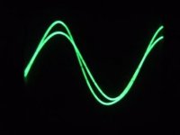
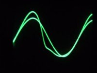
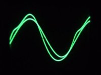
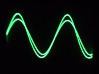
And 80Hz with compensation. Not only amplitude but also phase is corrected!
Using DC compensation freq response is much improved. Without compensation -3dB is at 80Hz. With compensation freq response is 0dB at 20Hz and -1.6dB at 20kHz. Cannot test lower than 20Hz with my signal generator, but it seems to go really low.
Overall quite promising results
- Elias
Using DC compensation freq response is much improved. Without compensation -3dB is at 80Hz. With compensation freq response is 0dB at 20Hz and -1.6dB at 20kHz. Cannot test lower than 20Hz with my signal generator, but it seems to go really low.
Overall quite promising results
- Elias
Attachments
Hello Erik,
The compensation is very simple. I feed DC current from voltage source of about 270mA to the 43V secondary through 100ohm resistor. I know it loads the primary a bit, better would be using current generator with high impedance. That would be one of the next steps I'm planning to do. However, the impedance level propably is not a big issue.
- Elias
Hi Elias
I don't think transformers like to be treated the way you supposed. If you are going to the trouble of adding a compensating DC current, why not operate two valves in Class A push-pull?
The problem is that the offset current does nothing for the signal, but adding another valve on the other primary winding would make use of that winding, give you twice the power, and reduce the DC all in one go.
cheers
John
Elias said:And 80Hz with compensation. Not only amplitude but also phase is corrected!
Using DC compensation freq response is much improved. Without compensation -3dB is at 80Hz. With compensation freq response is 0dB at 20Hz and -1.6dB at 20kHz. Cannot test lower than 20Hz with my signal generator, but it seems to go really low.
Overall quite promising results
- Elias
Well done ! Are you going to share the design ? I'm surprised at your upper rolloff . I got -0.5dB down at 20khz using a 6B4G into a 230:9+9 Talema 30VA unit .
cheers
316A
- Home
- Amplifiers
- Tubes / Valves
- Using mains transformer as output transformer