lehcim74, I would really like to have a pcb if its possible, if yes please tell me a price, otherwise can I have the schematic including the power supply? I would really love to use it for car too! Keep up your great work")
Hi Omokas,
Amplifier is still work in progress but the power supply is working OK.
Still intend to use it for mono subwoofer amplifier and trying some different
active pre-filters.
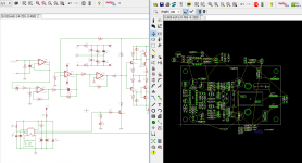
PSU is according PDF document attached.
Full schematic.pdf is with the class D amp.
(filter still needs some tuning to my believe)
PSU is made with ETD39 TDK PC40 material.
NP1=NP2= 5Turns
NS1=NS2=14Turns = about ±35V
(Mostly used smd parts on controlboard, that is why there are many 1P connector items used.)
Attachments
I have done try this amp, but i have a problem with DC offset,
i got -65mV and -54mV at other channel,
please help for reduce this DC offset,
BR//
Madde
They're good enough
They're good enough
Thanks sir for your answer, its save for speaker sir?


 merry CHRISTmass to you all
 Hi all,
i tried to get this amp working on a breadboard. I'm not sure if that makes sense at all because of the about 300kHz switching freq.
I run the amp at about +/- 33V with all components like the original schematic.
For very low input signals i can get about +/- 3V clean output signal at 4 ohms load.
When i try to go higher with the input the output gets distorted and lots current is drained from my negative power supply but output voltage remains the same. Only more and more noise.
The inductor gets pretty warm too. I tried about 30uH ferrite and iron powder cores, about the same problem.
PMOS gate signal: AC coupling, 5V/div, 1µs/div
NMOS gate signal: Same settings
Low level output signal: DC coupling, 2V/div, 0.2ms/div
Low level output signal noise: DC coupling, 2V/div, 2µs/div
Higher level output signal: DC coupling, 5V/div, 0.2ms/div
If you need more measurements i will provide them as soon as possible.
i tried to get this amp working on a breadboard. I'm not sure if that makes sense at all because of the about 300kHz switching freq.
I run the amp at about +/- 33V with all components like the original schematic.
For very low input signals i can get about +/- 3V clean output signal at 4 ohms load.
When i try to go higher with the input the output gets distorted and lots current is drained from my negative power supply but output voltage remains the same. Only more and more noise.
The inductor gets pretty warm too. I tried about 30uH ferrite and iron powder cores, about the same problem.
An externally hosted image should be here but it was not working when we last tested it.
PMOS gate signal: AC coupling, 5V/div, 1µs/div
An externally hosted image should be here but it was not working when we last tested it.
NMOS gate signal: Same settings
An externally hosted image should be here but it was not working when we last tested it.
Low level output signal: DC coupling, 2V/div, 0.2ms/div
An externally hosted image should be here but it was not working when we last tested it.
Low level output signal noise: DC coupling, 2V/div, 2µs/div
An externally hosted image should be here but it was not working when we last tested it.
Higher level output signal: DC coupling, 5V/div, 0.2ms/div
If you need more measurements i will provide them as soon as possible.
Hi all,
i tried to get this amp working on a breadboard. I'm not sure if that makes sense at all because of the about 300kHz switching freq.
I run the amp at about +/- 33V with all components like the original schematic.
For very low input signals i can get about +/- 3V clean output signal at 4 ohms load.
When i try to go higher with the input the output gets distorted and lots current is drained from my negative power supply but output voltage remains the same. Only more and more noise.
The inductor gets pretty warm too. I tried about 30uH ferrite and iron powder cores, about the same problem.
An externally hosted image should be here but it was not working when we last tested it.
PMOS gate signal: AC coupling, 5V/div, 1µs/div
An externally hosted image should be here but it was not working when we last tested it.
NMOS gate signal: Same settings
An externally hosted image should be here but it was not working when we last tested it.
Low level output signal: DC coupling, 2V/div, 0.2ms/div
An externally hosted image should be here but it was not working when we last tested it.
Low level output signal noise: DC coupling, 2V/div, 2µs/div
An externally hosted image should be here but it was not working when we last tested it.
Higher level output signal: DC coupling, 5V/div, 0.2ms/div
If you need more measurements i will provide them as soon as possible.
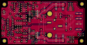
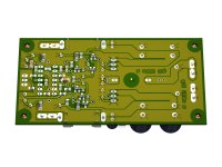
Post your pcb image bottom side and component side

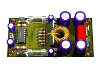
Nice work!Hi to all, this is my final amplifier SMPS +class D + speaker prot. It is working fine from several months.
View attachment 490173
Where we can find the schematic and pcb as built?
Last edited:
hello sir stewin,
is there any way to use this design at +/-50 volts?
mine worked for the voltage with original components but after a week started to fail. my pcb is double sided with dc protect. with 45volts it works fine but if i touch the volume pots on board then positive side mosfet dies burning output tracks and before dying it makes some sort of grunting noise. what maybe the issue?
D
Deleted member 148505
D
Deleted member 148505
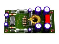
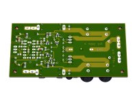
hi all finally smd version completed :UP:
instead of bc337 and 327 i used mmbt 3904 and mmbt 4403 any comments are highly appreciated
Dear stewin could you please share schematic or pcb layout files?
Much appreciated!!
hi all finally smd version completed :UP:  instead of bc337 and 327 i used mmbt 3904 and mmbt 4403 any comments are highly appreciated
but mmbt5401 and mmbt5551 i have and i will use. i use tl074 from ti (texas instruments) as they are the only ones which work with this circuit.
Attachments
-
200 watts standard smd pcb bottom.pdf29.5 KB · Views: 245
-
200 watts standard smd schematic.pdf37.2 KB · Views: 471
-
200 watts standard smd top components clear .pdf24.3 KB · Views: 262
-
200 watts standard smd bottom components clear .pdf18.3 KB · Views: 287
-
 200 watts standard smd.jpg358 KB · Views: 550
 -
 200 watts standard smd bottom.jpg298.8 KB · Views: 1,029
 -
 200 watts standard smd a.jpg345.3 KB · Views: 1,081
 -
 200 watts standard smd a bottom.jpg258 KB · Views: 1,121
 -
200 watts standard smd pcb top.pdf20.2 KB · Views: 242
- Home
- Amplifiers
- Class D
- Ultra Simple Class D