hi
is this amp ok?
how much have power?
good job
200 to 300W 4 ohm.
It has been built. It is good enough
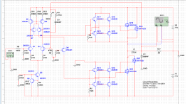
And this is complete design of UCD but consider DIYers who have supply material problem. It should be fine with it, but not the best. Tested.
IRF530 and +/-63 V is not a good combination. Burns out in the first minute or not, it depends on luck.
hi to all,
andrew or any one can simulate the schemantic and post the results, because my software got error.
thanks to all.
It will not work. Not just because 220 F is 1000000000000 times higher than you need, and R4, R3 are too small (or R10 is too big), but also there is not enough voltage for driving high side MOSFET, and there are some other minor mistakes also.
IRF530 and +/-63 V is not a good combination. Burns out in the first minute or not, it depends on luck.
IRF530 for up to 40Vdc. Agree
Typo error. Replace with 200V small gate charge mosfet. IRF640 at least
Last edited:
Hi,
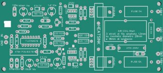
I want to share my project .
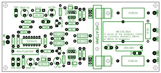
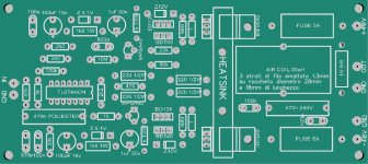
I prefer to use air coil to prevent saturation distorsion.
Build the coil on 28mm diameter support and 18mm lenght, with wire of 1.3mm.
About 30/32 turns.
No hot at max power.
I want to share my project .
I prefer to use air coil to prevent saturation distorsion.
Build the coil on 28mm diameter support and 18mm lenght, with wire of 1.3mm.
About 30/32 turns.
No hot at max power.
Attachments
Please can you share the schematic?Hi,
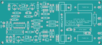
I want to share my project .
I prefer to use air coil to prevent saturation distorsion.
Build the coil on 28mm diameter support and 18mm lenght, with wire of 1.3mm.
About 30/32 turns.
No hot at max power.
I can't see the transistors oriendation(ebc) no at mpsa not bd139-140
Attachments
Last edited:
hi all any comments on the below link???
http://www.diyaudio.com/forums/class-d/205654-ultra-simple-class-d-48.html#post4446055
http://www.diyaudio.com/forums/class-d/205654-ultra-simple-class-d-48.html#post4446055
It looks brilliant,but as a diyer I wonder where to begin with for smd?hi all any comments on the below link???
http://www.diyaudio.com/forums/class-d/205654-ultra-simple-class-d-48.html#post4446055
Kartino, some time ago I found this: http://www.hypex.nl/docs/papers/AES118BP.pdf
Your UCD solutions seem to be based on this design, except that your feedback is slightly different. Would you care to elaborate why you deviated from the AES paper design?
I'm aware that the AES paper design is a concept, and it relies on the circuit delay to establish oscillation. Perhaps adding a delay to make things more predictable is a better way to go about this design.
I like this design, and most probably I'll build this one soon.
Last edited:
Kartino, some time ago I found this: http://www.hypex.nl/docs/papers/AES118BP.pdf
Your UCD solutions seem to be based on this design, except that your feedback is slightly different. Would you care to elaborate why you deviated from the AES paper design?
I'm aware that the AES paper design is a concept, and it relies on the circuit delay to establish oscillation. Perhaps adding a delay to make things more predictable is a better way to go about this design.
I like this design, and most probably I'll build this one soon.
The schema is not my design actually in term of topology. The reason of the feedback of mine is to minimize numbers of parts. It was a challenge in my group, what will looked liked the UCD with most minimum numbers of part. Please understand this reason behind.
For small amp, the kind of feedback is working just fine anyway. But it will need adjustment for dead time for soft to hard switch. Try to put higher value of R12, maybe put VR100 ohm in series with R12 and tune it. The mosfet shall be not to hot but clarity is OK, similar to Class AB biasing.
http://www.diyaudio.com/forums/class-d/205654-ultra-simple-class-d-49.html#post4461880
Last edited:
hi all any comments on the below link???
http://www.diyaudio.com/forums/class-d/205654-ultra-simple-class-d-48.html#post4446055
Hi Stewin,
What speed level maximum on simulation?
Indeed, this is also simple circuit, good to start and easy understanding for starter and maybe student. The same of my amp proposed.
The schema is not my design actually in term of topology. The reason of the feedback of mine is to minimize numbers of parts. It was a challenge in my group, what will looked liked the UCD with most minimum numbers of part. Please understand this reason behind. ...
OK, but why did you apply input signal on inverting input, and ground through 100 ohm to noninverting input? This way you introduced a significant imbalance in DC resistance between diff amp inputs. I bet DC output is far from 0. Which is a dangerous situation in case of single ended ClassD amplifiers because of supply pumping. If DC resistance drops (for example because load is coupled via transformer), very high current can start to flow to the positive supply rail, destroying the amp.
On the noninverting side you could have been achieved a much higher input impedance (27 kohm) along with a theoretically perfect balance.
Oh, I almost forgot to mention: in your circuit signal source impedance can affect oscillation badly.
I don't know if there is any good effect related to this choice.
Hi,
can anyone help me with the IRS20957? Wherefore do i need the comparator in the circuit?
I want to drive my IC with a PWM Signal from a DSP. The most circuits that i found here in the forum include a comparator, but when i look at the IR reference Design and some other circuits (like this one: http://media.digikey.com/photos/rdl/iraudamp6_schematic_4_full.png) they dont use a comparator. Just straight the PWM signal into the "In" Pin. Totime i am struggeling with a DC at the Output, and i dont get a proper startup. I am testting with a 260kHz 10Vpp 50% Duty PWM Signal from my Generator.
Please help me, thanks")
can anyone help me with the IRS20957? Wherefore do i need the comparator in the circuit?
I want to drive my IC with a PWM Signal from a DSP. The most circuits that i found here in the forum include a comparator, but when i look at the IR reference Design and some other circuits (like this one: http://media.digikey.com/photos/rdl/iraudamp6_schematic_4_full.png) they dont use a comparator. Just straight the PWM signal into the "In" Pin. Totime i am struggeling with a DC at the Output, and i dont get a proper startup. I am testting with a 260kHz 10Vpp 50% Duty PWM Signal from my Generator.
Please help me, thanks
- Home
- Amplifiers
- Class D
- Ultra Simple Class D