Hi dear jester 87, could you share the schematic of new protection circuit, with high/low side protection? I would like to use it in a new project, i would like to understand itCurrently working on 250W @ 4 ohms version using IRF6218/IRFB33N15D.
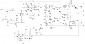
Reworked protection circuit, high/low side protection. Double sided PCB.
Will share schematics after I tested the prototype.")
D
Deleted member 148505
Hi dear jester 87, could you share the schematic of new protection circuit, with high/low side protection? I would like to use it in a new project, i would like to understand it
download here
Attachments
thanks jlester . can that protection it support 2 ohms @ +/- 45vlts??
Greetings mr.jlester
Pls share pcb files in pdf formate
Thank you
Thank you so much jlester87, I'm gonna use it in my new design...
download here
Thank you so much jlester87, I'm gonna use it in my new design...
D
Deleted member 148505
Greetings mr.jlester
Pls share pcb files in pdf formate
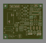
Here's a quick layout, it's not the best but it will work. Size is less than 10cm x 10cm so manufacturing will be cheap.
You can put VER2923-333KL, ICE 1D23A-330M, T106-2, T106-6 (33uH)
I cannot share PDF because it is 2 layer and some traces are very thin.
Attached gerber file.
Attachments
D
Deleted member 148505
D
Deleted member 148505
download here
hi jlester thanks again for the share . how and where can i adjust the current for the amp protection?? i wanted to push the amplifier to 18amps.
Attachments
Last edited:
D
Deleted member 148505
Hi Stewin, you can lower R41 to 1k
or lower the value of current sense resistors since they will dissipate more power.
thanks jlester for the quick response . meaning if i want more like 30amps i can reduce both R41 and R42 to about 330ohms and use two parallel 0.1R in both +/- .

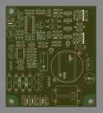
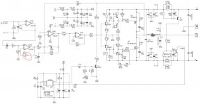
Shouldn't R5 be 33k if goal is to reduce IC2D offest?
hi mac , here is a photo for all to see better. r5 is circled in red
Attachments
meaning if i want more like 30amps i can reduce both R41 and R42 to about 330ohms and use two parallel 0.1R in both +/-
Hi stewin,
I = (550mV/CSR) x (R37xR42/R42)
here I = (0.55/.05)x (1kx10k/10k) = 11A
I= 0.55/.033 x 2.2k*1k/1k = 36A
regards
manoj
Last edited:
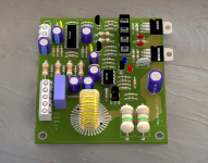
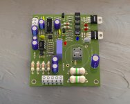
hi all . below are links to my 200watts smd version all i have tested and are working fine.
have fun all . and to GOD be all the glory
diysmps
diysmps
http://www.diyaudio.com/forums/class-d/205654-ultra-simple-class-d-48.html#post4446055
In my amp BD139 & 140 are getting real hot. Is that case with your design or is it usual? The schematic is same no changes.
Any word of advice?
Thanks in advance
but mmbt5401 and mmbt5551 i have and i will use. i use tl074 from ti (texas instruments) as they are the only ones which work with this circuit.
In your layout GND is treated very badly, has very high inductance between different points of it. You need a very much cleaner GND to avoid interferences.
thanks jlester for the quick response . meaning if i want more like 30amps i can reduce both R41 and R42 to about 330ohms and use two parallel 0.1R in both +/- .
No, only Rcs should be decreased to avoid excessive dissipation on them.
"(lower R41 to 1k) or (lower the value of current sense resistors)"
- Home
- Amplifiers
- Class D
- Ultra Simple Class D