hi all , it is quiet here. please guys post pictures of your projects.
i wanted to ask , can lm324 be used in this amp instead of tl074 ?
Probably not.
https://www.ti.com/lit/ds/symlink/tl074.pdf
https://www.ti.com/lit/ds/symlink/lm324.pdf
GBW for the 072 is 3MHz vs 1MHz for the 324. More importantly slew rate for the 072 is 13V/uS vs 0.5V/us for the 324
At least one of the amplifiers is being used as a comparator and delays in circuit contribute to the self oscillation and the frequency at which it occurs. The 324 might try to work but even if it manages to give clean gate transitions, it probably won't, the amplifier will be switching at a very low frequency.
Of course you could try one and tell me I guessed wrong
")
Inverting integrators require fast opamps, and PA-s are expected to provide low distortion. LM324 falls short on both.
With speed in mind, guess a better integrator would be the 2C non-inverting one, but that would require it to be followed up by an inverting amplifier and a comparator.
With speed in mind, guess a better integrator would be the 2C non-inverting one, but that would require it to be followed up by an inverting amplifier and a comparator.
Hi all,
this is my first time to post here, i want to share my work and seeking for help as i this PCB but for some reason it is not working so any help?
Thanks a lot.
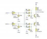
the amplifier should work well , please check your bc337/327 also is the quality of your tl074 good?
please post more pics ,even of your power supply and the dmm reading
Class d build
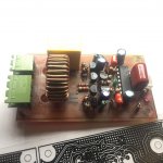
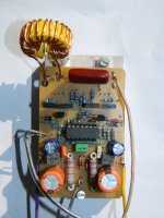
Thank you Stewin for the quick response, the problem caused by the filter inductor i had to change the core (from a green to a yellow one) and add more turns, unfortunately i don't have LC meter to measure inductance and i don't know if it is a ferrite or iron powder core and so i cannot calculate anything!.
Anyway it worked very well, one thing i am not quiet sure of is the heat dissipation of small signal transistors (Q4 and Q6) is that okay??? they get warm but i can stand touching them for a while but i can tell they get really warm.
PSU is +- 39 Volts.
Will post more pictures and readings soon.
Thank you
the amplifier should work well , please check your bc337/327 also is the quality of your tl074 good?
please post more pics ,even of your power supply and the dmm reading
Thank you Stewin for the quick response, the problem caused by the filter inductor i had to change the core (from a green to a yellow one) and add more turns, unfortunately i don't have LC meter to measure inductance and i don't know if it is a ferrite or iron powder core and so i cannot calculate anything!.
Anyway it worked very well, one thing i am not quiet sure of is the heat dissipation of small signal transistors (Q4 and Q6) is that okay??? they get warm but i can stand touching them for a while but i can tell they get really warm.
PSU is +- 39 Volts.
Will post more pictures and readings soon.
Thank you
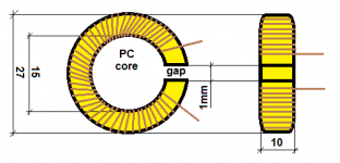
the heat in the small trannies is ok . but if you are using a yellow white core or green blue core , cut 1mm gap one side of the ring with a hacksaw and coil 33turns.
have fun
the heat in the small trannies is ok . but if you are using a yellow white core or green blue core , cut 1mm gap one side of the ring with a hacksaw and coil 33turns.
have fun
like the below
Attachments
thanks mark ,
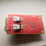
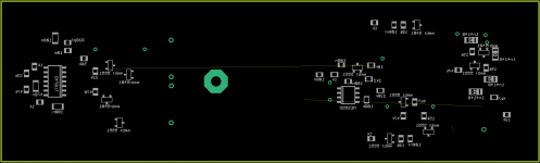
hi all , just finished the fully smd version . please check if there are any errors .
also i have added a relay for on delay and dcp also over current protect is on .
where should I add the over temperature ?
if there are any updates ideas or suggestions ,they are highly appreciated ,please post them here . all files are below
core used can be t-106 to t-157
thanking you all in advance steve
Attachments
-
gtG 200 watts standard smd ver 2.0.zip151.2 KB · Views: 81
-
gtG 200 watts standard smd ver 2.0 board 2.pdf99.5 KB · Views: 117
-
 gtG 200 watts standard smd ver 2.0 board.png61.2 KB · Views: 272
 -
gtG 200 watts standard smd ver 2.0 board 1.pdf72 KB · Views: 92
-
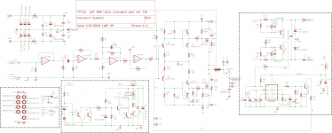 gtG 200 watts standard smd ver 2.0 schematic.png67.9 KB · Views: 421
 -
gtG 200 watts standard smd ver 2.0 schematic.pdf47.9 KB · Views: 122
hello all, the smd version of this amp with protection . the eagle file is for eagle 9 onward. old eagle will not open the pcb project , have fun all
Attachments
-
200wt dual smd standard ver1.zip1.3 MB · Views: 117
-
200wt dual smd standard ver1 pcb bottom.pdf50.6 KB · Views: 118
-
200wt dual smd standard ver1 pcb top.pdf38.3 KB · Views: 118
-
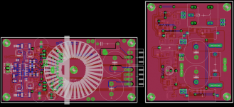
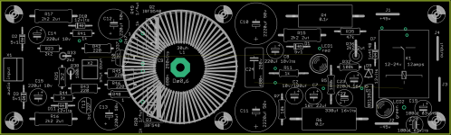 200wt dual smd standard ver1 top full components.png100.6 KB · Views: 472
 -
 200wt dual smd standard ver1 bottom clear components.png26.9 KB · Views: 473
 -
200wt dual smd standard ver1 pcb full.pdf685.4 KB · Views: 126
-
200wt dual smd standard ver1 schematic.pdf44.3 KB · Views: 148
Last edited:
hello all, the smd version of this amp with protection . the eagle file is for eagle 9 onward. old eagle will not open the pcb project , have fun all
hi Stewin
have are you?
can you please share eagle library used in this amp too ?
i need it to convert eagle doc to altium doc
thank you
Hi stewin,
did you check DC protect, something wrong in your schema.
Regards
MANOJ
and i have etched the pcb hi Stewin
have are you?
can you please share eagle library used in this amp too ?
i need it to convert eagle doc to altium doc
thank you
eagle files are in the zip folder , i have shared
eagle files are in the zip folder , i have shared
thank you but i mean eagle library you used to design this schematic and pcb
altium in convertion need that
- Home
- Amplifiers
- Class D
- Ultra Simple Class D