So catch , diysmps
The Inductor5100 is for ferrite cores , and InductorRing is for iron- , metall-powder cores.
Other progs are for design and calculation for many types of SMPS.
Any questions ? Ask me or Starichok51 (starichok in Russian means oldman , he's more than 60 years old) , if you like his programs , you may donate him (how ,you can find in "about")/
So catch , diysmps
The Inductor5100 is for ferrite cores , and InductorRing is for iron- , metall-powder cores.
Other progs are for design and calculation for many types of SMPS.
Any questions ? Ask me or Starichok51 (starichok in Russian means oldman , he's more than 60 years old) , if you like his programs , you may donate him (how ,you can find in "about")/
Hi Dimonis.
Very cool calculators, thank you so much for pointing out the link.
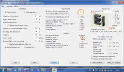
Here is an example for EI33 , 30uH , 20Amp - it means about 800W RMS power at ideal +-80V supply.
The indicated gap (3mm), is this the gap in centerleg or gap on all three legs?
Always calculates one gap in madnetic flux.
And it's your decision to divide it to multiple according to core type.
Thank you.
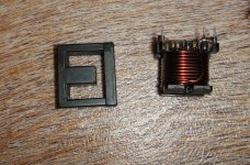
Did make EI-33 based on calculator but 20Trns already did give me too much µH with ONLY E-part onto bobbin.
Had to reduce windings to about 15Trns and then made a gap of about 1.75mm on ALL three legs to get somewhere near 30µH.
Will build the amplifier within soon and let you know the outcome
")
I made calculations and wound many-many inductors and transformers by this software , and the accuracy was not more than +-10%.
How do you measure inductance?
PS My inductor on EI33 , 50uH , gap ~4mm.
Did you use your inductor within the design of this thread?
I was aiming for the 30µH, but that's not that important or what?
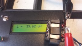
I'm measuring inductance by oscilloscope by applying voltage to the choke
and by setting current flow through the choke I can derive the inductance by an equation. This setup is working OK, let me assure you.
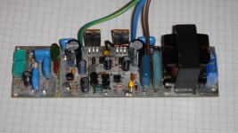
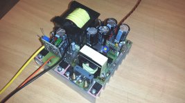
Finished amp with power supply
My first attempt at building an amplifier.
Some experience with power supplies, so build a
12Vdc to ±35V converter on the same board
to use as car amplifier.
Is it correct that the output is 180° phase shifted in regards
to input signal?
My first attempt at building an amplifier.
Some experience with power supplies, so build a
12Vdc to ±35V converter on the same board
to use as car amplifier.
Is it correct that the output is 180° phase shifted in regards
to input signal?
Attachments
My first attempt at building an amplifier.
Some experience with power supplies, so build a
12Vdc to ±35V converter on the same board
to use as car amplifier.
Is it correct that the output is 180° phase shifted in regards
to input signal?
What core You use for output filter ?
is the co gap or gapless ?
Is the core get hot ?
Btw is a good looking amp I hope its perform well too
What core You use for output filter ?
is the co gap or gapless ?
Is the core get hot ?
Btw is a good looking amp I hope its perform well too
Output filter is TDK PC40 gapped (EI-33)
Core ain't getting hot, wire heats up a little so need to work
on that.
Only tested with sine-wave generator so far and 4Ohm load.
Need to get my hands on some suitable audio input and speaker
output
use litzwire and it will not heat up so much
used 17strands of ø 0.315mm, so I'm guessing that's not the problem.As indicated, it warms up (not heating up) with both no load and load as output is always switching regardless input signal amplitude.
Heating up to 100° C at full load is normal. And something about 50-70° C at idle.
Seems about correct then
But what about the inverse output in regards to input signal (180° phase shifting), is that correct.
- Home
- Amplifiers
- Class D
- Ultra Simple Class D