I realized i still have a recording of the amp i posted: Sound recording of diy class d amp - YouTube <-- thats what my supersimple class d amp sounded like.
200 watts into 4 ohms with just 2x40V rails sounds a bit too good to be true, bvut then again a class ab amp with 2x40V rails gives 150W into 4 ohms(onaudio symef as example), so maybe.
The amp i posted is just a lil 2x5W one running off a 2x15V psu though.
thanks tekko,
how much variations can be done in voltage with this amp....as there can be a fluctuations of +/-10 volts during operating....the voltage can go above or near +/-50 volts can this amp bear this
I have no idea what voltage the amp this thread is about can take, i'd have to build and test it to be able to tell.
so can u do so,,,,,,or i suggest u ask any of your friend to do so whoever has built it...and get the response of amp....and can u tell me how to meaasure the oscilating frequency and also dead time....i have an old oscciloscope but dont have much knowledge to use that
What i said is derived from my own measurements of class D amplifiers.Distorsions should be measured with low pass filter (like AES filters)That is true for a linear amplifier, but not for a switching amplifier.
Above 1kHz you also have to take into account the power fluctuations caused by the carrier remains at the speaker output, which will greatly affect the measured THD, i've seen more than 100% THD at 20kHz in simulations due to the ripple caused by the carrier residual.
.
Using a second order filter will help with this problem.Yes i know the inertial mass of the tweeters dome will not be able to move that fast, but it will still affect the sound, the effect this ripple has on say a cymbal is similar to that of crossover distorion, the sound of breaking glass.
.
For now the main source of distorsions in my designs is interchannel and interstages EMI interference that i have yet to fully solve,the effects are far uglier than residual distorsions .
Last edited:
Yes i can...use yor time base and voltage per division.
Tutorial here:
Oscilloscope AC Voltage Measurements
Deadtime is trickier to measure,it depends on the waveform.
Tutorial here:
Oscilloscope AC Voltage Measurements
Deadtime is trickier to measure,it depends on the waveform.
Last edited:
Using a second order filter will help with this problem.
Unfortunately this equals alot of phase shift, so if theres a post filter feedback loop, this NFB loop will be rendered almost useless.
However if the amp uses pre filter feedback only, then the output filter can be anything, it shouldent really distort the signal any more than the output inductor on a class AB amp does, even though the purpose is totally different.
As long as the signal derived from the output PWM through the NFB voltage divider matches that of the input signal, the post filter signal, while phase shifted should closely match the input, only 10-20 times larger.
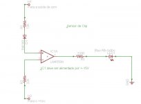
Hello guys, I put this sensor clip and it worked fine, did a test at 60hz, when the wave begins to be rectangular in output (Clip), the LED lights. Among the opamp inverting input (pin 2 and 3), goes a ceramic capacitor, but I do not find a value that could be more normal to me, so I did without it, and it worked fine. The resistor values depend on the value of supply, which in my case + - 25, but I think that this same scheme works very well in + -40 V. ")
Attachments
i did the same schematic provided in this amp....but instead of 820p i used 1n2...what diff can it make.....instead of bd 139 140 i used A1837 C4793.....there was all positive volt in out.....gate of mosfets showed square wave signals on that but no output....so can anybody plz help me with this issue ....
My guess is that your mosfets are dead. Allthough failing open circuit is rare but it does happen.
Also make sure you have wired them right.
how can this be.....i tested the mosfets after disconnecting them...they were all fine but all problem was that it dint worked and there was no short to be detected
Do you guys make your own circuit boards or buy them someplace? I'd like to build a pair of these amps. Thanks
we make them
Do you guys make your own circuit boards or buy them someplace? I'd like to build a pair of these amps. Thanks
watch you tube on tutorials home made pcb and download artworks of any project you like Bless GOD and have fun.
can Lm324 work well instead of TLO74...in this ultra simple design
it woun't have clarity as tl074/84
- Home
- Amplifiers
- Class D
- Ultra Simple Class D