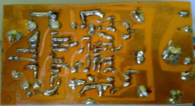
Hello people, okay? I just set up my prototype in a proto-board. As I said I used a complementary pair (irf640 and IRF9640), although I'm not using a source of + - 60, but one of + - 25.
I'm impressed great sound quality I got, and how friends asked you guys post here some parameters that you guys have questions. First notice that I use an oscilloscope for PC, what do not cease to be a great tool and it got the values of the parameters.
Again, these are values that got in my equipment, using sinusoidal signal generator with a frequency of 1khz:
Power Supply: + - 25VDC (50Vdc).
Power (rms): 112.5 @ 8ohms
Sensibility: 0.8 V
Freq range: 20 to 18khz.
input impedance: 47kohms.
output impedance: 4ohms.
THD @ 1kHz: 0.18%
THD + n @ 1khz: 30.4%
even more
thanks for the simulation GOD bless you a lot
0.1% THD at 1kHz, eww thats awful, if it was at 20kHz, it'd be ok but this is just terrible.
At 20kHz the THD must be atleast 10% if not more, considering this thing only oscillates at a few hundred kilohertz.
I may experiment with this scheme, but if i do so, the last opamp in the chain will be replaced with a comparator to speed things up.
As fumac already discovered, a carrier of atleast 1MHz is required before class d even starts to get anywhere near fullrange use with any acceptable sound quality.
0.1% THD at 1kHz, eww thats awful, if it was at 20kHz, it'd be ok but this is just terrible.
At 20kHz the THD must be atleast 10% if not more, considering this thing only oscillates at a few hundred kilohertz.
I may experiment with this scheme, but if i do so, the last opamp in the chain will be replaced with a comparator to speed things up.
As fumac already discovered, a carrier of atleast 1MHz is required before class d even starts to get anywhere near fullrange use with any acceptable sound quality.
") hi tekko long time my friend welcome back . this amp sounds nice in real life pls simulate again
hi tekko long time my friend welcome back . this amp sounds nice in real life pls simulate againmy own pcb
Hi every body
this is my pcb
is this ok?
stewin
View attachment stewin class d.zip
Hi every body
this is my pcb
is this ok?
stewin
View attachment stewin class d.zip
0.1% THD at 1kHz, eww thats awful, if it was at 20kHz, it'd be ok but this is just terrible.
At 20kHz the THD must be atleast 10% if not more, considering this thing only oscillates at a few hundred kilohertz.
I may experiment with this scheme, but if i do so, the last opamp in the chain will be replaced with a comparator to speed things up.
As fumac already discovered, a carrier of atleast 1MHz is required before class d even starts to get anywhere near fullrange use with any acceptable sound quality.
Professionals have seen class D digital amplifier Over 1K5 watts, which has thd 0.9. For me, thd not reaching more than 1% tot, can now be considered an optimal amplifier. Try to build this circuit tekko, you will see that it has excellent sound quality. By chance you're an audiophile professional? If it is not, please disregard this 0.1% thd.
We know notting abut the load currents..he has to retest the amplifier with various output currents as i said.0.1% THD at 1kHz, eww thats awful, if it was at 20kHz, it'd be ok but this is just terrible.
At 20kHz the THD must be atleast 10% if not more, considering this thing only oscillates at a few hundred kilohertz.
Thd will only increase from 0.2% to max 1% at 20 khz which are inaudible anyway.
That is true for a linear amplifier, but not for a switching amplifier.
Above 1kHz you also have to take into account the power fluctuations caused by the carrier remains at the speaker output, which will greatly affect the measured THD, i've seen more than 100% THD at 20kHz in simulations due to the ripple caused by the carrier residual.
Yes i know the inertial mass of the tweeters dome will not be able to move that fast, but it will still affect the sound, the effect this ripple has on say a cymbal is similar to that of crossover distorion, the sound of breaking glass.
Heres a super simple low power class d simulation running 1-2MHz carrier: http://i.imgur.com/Fy5yD.png
The sine wave is 20kHz, and still theres quite a bit of ripple on the peaks of the power waveform.
Though a THD of only 1% at 20kHz is quite possibly very good for a class D amplifier, atleast one this simple.
Theres likely a reason why commercial class d amplifiers such as B&O ICEPower are extremely complex with alot of error correcting circuits and multilevel modulation and what not.
I have measured the inductance T106-2 with 28 turns my RLC meter says 3,63milliHenry it's possible?
I've tried to change indutor from t106-2 to t130-26, but I noticed that both heats around 75-80 ° C and the output power did not exceed 20w, the capacitor value is 1uF but the rlc meter with -26 says 15uH
I've tried to change indutor from t106-2 to t130-26, but I noticed that both heats around 75-80 ° C and the output power did not exceed 20w, the capacitor value is 1uF but the rlc meter with -26 says 15uH
I build this circuit but with a TC4422 gate driver as output stage a few years ago.
http://diymania.hv4all.com/selfosc classd/new/MCD/stereo/splitsupply/outputstage.jpg
http://diymania.hv4all.com/selfosc classd/new/MCD/outputwaveform.jpg <-- the PWM out, 2MHz.
http://diymania.hv4all.com/selfosc classd/new/MCD/stereo/TAPSimplePower.jpg
This amp sounded ok but got very hot, but it had nothing on even a cheap chipamp from a set of computer speakers, and compared to a real stereo system, it sounded like a mp3 with a 8kHz sample rate in comparison, but somehow it did earn me my first loud bass complaint despite beeing only a few watts of power in 4 ohms.
i did run a test on it though: RightMark Audio Analyzer test : MHzclassd
And for reference: RightMark Audio Analyzer test : [MME] Line 1/2 (Audiophile USB (tm)) <-- the soundcard on its own.
- Home
- Amplifiers
- Class D
- Ultra Simple Class D