also try this link diysmps
mr stewin
i do not know why but i can not open diysmps site.!!!!!!
may be it was damaged.
may be that site was filtrler in my country and internet isp.
thanks for your helping
can it be used in smps also.
yep, this circuit is used in smps(this case power supply based in a SG3525).
The operation is very simple:
the diode d1 is connected to some opamp (tl072 for example),configured as a comparator so that a greater variation in voltage at the output of MUR160, the comparator to disconnect the SG3525 through the optocoupler
stewin, please make measurements(THD, IMD and SNR)..any evaluation based on human senses is irelevant in my opinion.
also corect your schematic, R7 has no function.
thanks for sharing

Still nobody measured the performance of this circuit yet?
Still nobody measured the performance of this circuit yet?
I'll build today this amplifier, but with a power supply with +- 60V using
irf9640 and irf640...

I'll build today this amplifier, but with a power supply with +- 60V using
irf9640 and irf640...
pls post results and monitor heating components
yes of course but confirm pins.Hi Stewin can I use mpsa92 instead of 2n5401 in the amplifier I have the 2n5551?
Dead time is controlled by R12.This type of circuit does not need to add a deadtime?
Attachments
Hi at all!
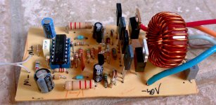
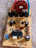
This is my pcb of this amplifier from Stewin project
I've a problem the output will feel very little in the speaker.
I'm using +-38V DC from project89 of Elliot sound (step up converter from 12V to +-40V), in the tl074 I've 4,60V, I've tried to change the 2,2k resistors with 1k but nothing has changed.
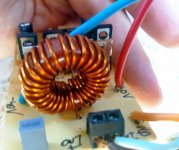
The toroid it's a 106-2 it's red on all the faces.
The speakers have 2ohm
This is my pcb of this amplifier from Stewin project
I've a problem the output will feel very little in the speaker.
I'm using +-38V DC from project89 of Elliot sound (step up converter from 12V to +-40V), in the tl074 I've 4,60V, I've tried to change the 2,2k resistors with 1k but nothing has changed.
The toroid it's a 106-2 it's red on all the faces.
The speakers have 2ohm
Attachments
Last edited:
stewin:
Yes..that r12...and tl074 has a very slow rise/fall time and that creates deadtime also.
abarth92:
tri this:
1.Inject signal directly into pin 2 at tl074.If this doesn't work try:
2.Disconnect speaker and conect 200 ohm load. Disconect R12 .Connect T1 and T2 comman base to to +40 volt and -40 volt with 4.7 kohm resistor.See if you have normal output swing(+vcc and -vcc).
Last edited:
abarth92 the amp works the way it is without modifications please check your soldering and components . i even posted pictures of my amp at diysmps
>>>>>and i have noted you are using single sided pls ground properly because the top layer connects ground (0vlts) to the rest of the board<<<<<<<<<<<<< when i used single sided i had use jumpers to make sure all ground planes are connected.
>>>>>and i have noted you are using single sided pls ground properly because the top layer connects ground (0vlts) to the rest of the board<<<<<<<<<<<<< when i used single sided i had use jumpers to make sure all ground planes are connected.
Last edited:
Hey guys, just a small observation that may go unnoticed by many who will try to assemble and are not going to get, I hope you take this into consideration:
2n5551 transistor is different from 2n5551C, only the pins, see datasheets
wow thanks that's why on eagle layout are different i thought the software had error Hello people, okay? I just set up my prototype in a proto-board. As I said I used a complementary pair (irf640 and IRF9640), although I'm not using a source of + - 60, but one of + - 25.
I'm impressed great sound quality I got, and how friends asked you guys post here some parameters that you guys have questions. First notice that I use an oscilloscope for PC, what do not cease to be a great tool and it got the values of the parameters.
Again, these are values that got in my equipment, using sinusoidal signal generator with a frequency of 1khz:
Power Supply: + - 25VDC (50Vdc).
Power (rms): 112.5 @ 8ohms
Sensibility: 0.8 V
Freq range: 20 to 18khz.
input impedance: 47kohms.
output impedance: 4ohms.
THD @ 1kHz: 0.18%
THD + n @ 1khz: 30.4%
even more
Last edited:
- Home
- Amplifiers
- Class D
- Ultra Simple Class D