Ultimate Twin TDA1541a Non-oversampling DAC with tube buffer & reclock set...........
Dear dw1narso,
I cannot get your email. pls re-email to me for detail.
or try to email my another account.
tda1541a@hotmail.com
my pocket pc sometimes cannot login yahoo & my netvigator.com.
but looks hotmail was good to easy check.
thx
thomas
Dear dw1narso,
I cannot get your email. pls re-email to me for detail.
or try to email my another account.
tda1541a@hotmail.com
my pocket pc sometimes cannot login yahoo & my netvigator.com.
but looks hotmail was good to easy check.
thx
thomas
finneybear said:
Hi Kiyull
It will be great if your friend can come out some good solution. We need something rigid enough yet with a good Q value to damp the vibration.
Have you replaced the XO? Also most parts used on CD-PRO2 are of very low quality, industrial grade parts. Try to replace those e-caps with OS-Con SVPs. You will be amazed to hear the difference.
Be honest to you, I do not feel Elso's circuit is a good idea. First of all, 2N4401's bandwidth is still a bit low. I2S does not have any error correction capability, to run for 70cm, differential line will be the way to go. The interface design will become very complex. In this case, probably I will just go for SPDIF!
Those PIO caps looked familiar to me hence the question. I also got lots of ex-Soviet PIO caps from eBay, probably from the same guy?The silver mica caps he's selling are very good, too. I still feel PP caps are the way to go for those decoupling caps due to its better HF performance. Those caps are the by-passing caps for the 6 small 2bit DACs per channel running in the DEM (dynamic element matching) config. The decoupling caps have to remove the HF switching noises as well as supply immediate current. This is why you can not make the caps too big; this will ruin the resolution; they can not be too small either, you will lose the dynamics. My current solution is to use 0.1uf PP || 0.01uf PP for the lowest 2 caps. 0.1uf PP || 0.1uf PP for the mid 2 caps, BG NX .47uf || 0.01uf PP for the upper 3 caps. Still, your finding with PIO is very interesting. Good to know it has a soft and smooth sound. I will try your setup some time.
I also use two 1541 S2 on the DAC. The +-18V is provided by a separate board. I will post the photos soon.
-finney
Hi Finney, I don't know why I missed your post. Sorry about that.
Anyway, thank you very much for your kind comments for various subjects which are my current interest.
I think that the modification of module suspension is not good idea since many cables, including a bit rigid digital cable, are still connected to the module. Because of this I have to make a transport and a DAC by two boxes.
In this case I have to decide the connection, i2s or spdif. Mine is something like experimental one, but the others ( 2 or 3 CD-PRO2)should be rigid. I tested Elso circuit roughly with different TR. It works, but I returned. Probably, I have to use direct and shortest i2s or SPDIF as you mentioned.
BTW, is there any theoretical reason for the shorter (15cm) i2s cable ?
How about SPDIF cable with reclocking of Thomas? Is it same theoretical quality with shorter i2s? ( I am not expert in this field, and I am just soldering as is with minor modification using Ohm's law etc.)
If the theoretical sound quality of SPDIF with reclocking is the same as that of i2s, at least, I will go with SPDIF. Please advice me for this.
I didn't repalce XO on the module. Be honest with you, I am afraid of the replacing. I opend module and there are many 47u/25V cap. Are those the cap you mentioned? I may be able to replace those with OS SVP, since I reserved one module for the accident.
For the comments about the PIO, you are right. I may lose HF resolution. The system in my lab is not so good as usual: old tr integrated amp with almost vintage speaker!! It has soft and smooth sound like as analog. Next transport and DACs shoud be tested extensively at other place.
I was impressed by your decoupling solution : two DAC boards are at hand and I will follow your solution for one of two. Do you mean that the upper 3 caps are pin no. 7, 8, and 9 (22,23, and 24 )?
Thanks again
Kiyull
Ultimate Twin TDA1541a Non-oversampling DAC with tube buffer & reclock set...........
hi all,
The coming despatch days will a little bit delay because my dear friend, finney was advise me to test the Belden 1505a. I borrow one from my friends & immediately gather some of my friend to test with this cable. I would like to say this is a interesting cable because had different taste which compare with gotham 10070 pro.digital cable.Due to 10070 is the standard parts of the DAC. i will added this cable into the kit....................free of charge.
But the cable will arrived my hand on staurday. I will immedately added into parcel & post.
The very good quality BNC sockets was arrived my hand. i will prepare full set diy digital cable to diyers. price will e1.m digital cable with full set BNC socket, BNC to RCA adapter. totally will USD 50.
photos will upload later.
thx
thomas
Not hampered by any Knowledge (as my Father used to say)
2N3958A which has higher bandwith does not give better results. If you know how a transmission line works you would not suggest using a shorter cable. I did not see any signal loss at the DAC.....In fact the cables could be much longer.
kiyull said:
Hi Finney, I don't know why I missed your post. Sorry about that.
Anyway, thank you very much for your kind comments for various subjects which are my current interest.
I think that the modification of module suspension is not good idea since many cables, including a bit rigid digital cable, are still connected to the module. Because of this I have to make a transport and a DAC by two boxes.
In this case I have to decide the connection, i2s or spdif. Mine is something like experimental one, but the others ( 2 or 3 CD-PRO2)should be rigid. I tested Elso circuit roughly with different TR. It works, but I returned. Probably, I have to use direct and shortest i2s or SPDIF as you mentioned.
BTW, is there any theoretical reason for the shorter (15cm) i2s cable ?
How about SPDIF cable with reclocking of Thomas? Is it same theoretical quality with shorter i2s? ( I am not expert in this field, and I am just soldering as is with minor modification using Ohm's law etc.)
If the theoretical sound quality of SPDIF with reclocking is the same as that of i2s, at least, I will go with SPDIF. Please advice me for this.
I didn't repalce XO on the module. Be honest with you, I am afraid of the replacing. I opend module and there are many 47u/25V cap. Are those the cap you mentioned? I may be able to replace those with OS SVP, since I reserved one module for the accident.
For the comments about the PIO, you are right. I may lose HF resolution. The system in my lab is not so good as usual: old tr integrated amp with almost vintage speaker!! It has soft and smooth sound like as analog. Next transport and DACs shoud be tested extensively at other place.
I was impressed by your decoupling solution : two DAC boards are at hand and I will follow your solution for one of two. Do you mean that the upper 3 caps are pin no. 7, 8, and 9 (22,23, and 24 )?
Thanks again
Kiyull
2N3958A which has higher bandwith does not give better results. If you know how a transmission line works you would not suggest using a shorter cable. I did not see any signal loss at the DAC.....In fact the cables could be much longer.
kiyull said:
Hi Finney, I don't know why I missed your post. Sorry about that.
....
Kiyull
Hi Kiyull
I thought your friend would build a sub-platform just for the CD-PRO2M module alone? The connections to CD-PRO2M are all done through the Molex (or more precisely, the JST) sockets. You can use flexible cables for this part. For instance, the SPDIF outputs can be shielded silver wire going to another digital output board so you will not encounter any rigid cable problem?
Replacing the XO on the CD-PRO2M is really easier than what you think. I have seen lots of people done that before and it is a must-do. CD-PRO2M are just full of crap industrial parts. If you have a decent tweezer solder, replacing those 47uf caps with SVP should be easy too. And you will be amazed to hear the difference.
I2S is just a protocol between chips. You know, like the protocol between CPU and memory control chip? It's meant to be done on a PCB, in the shortest distance. If you want to do a transimssion line for it, there will be lots of things to consider. First, you have to provide some sort of modulation for the siganls, give them certain driving capability. On the receiving end, you need to provide some sort of recovery circuit because the signals will change shape after they go through the long line. Another major issue with I2S is that the clock signal is going through it. The frequency is in the MHz range. If you want to preserve the perfect square wave shape, you will need a line which has a 500MHz+ bandwidth, or you will need to play some tricks on the recovery circuit. Then you still have this clock skew and jitters issues. SPDIF has the same problems but at least every component along the SPDIF line is better understood. For example, when you use CS8414 for the recovery, you know the clock will have a 200ps jitter. How much jitter it will be when you use a home made recovery circuit for I2S or no recovery circuit at all?
I am not against listening test; however, from engineerings point of view, when you know there's an engineering problem, at least address the problem in the correct engineerings way. Also listening tests can give you misleading results. You may have tried 100 different ways and come to, you think, the one best solution; however, what if all of those 100 solutions are all bad solutions?
Either I2S or SPDIF will bring in jitters. In SPDIF's case, if the signals quaity is good, probably you will get a 300-400ps jitter on the output of CS8414. With a simple FIFO and good XO, you should be able to reduce the jitter to 30ps or less. Even Thomas'es simple reclocking will give you good result, assume the outputs from CS8414 are not bad. So it's crucial to make sure the siganl output from CD-PRO2 is good, and the transimssion line is good. In other words, reclocking is just part of the solution.
How about the sound difference? I have heard on board I2S DAC make sound worse than an external DAC through SPDIF, pretty much the same DAC, just different receiving end. So it all depends on whether you do the thing right.
As for the order of the decoupling caps. You first locate the pins where Thomas paralleled with OS-Cons. These two are the decoupling caps for the upper 10 bits. Then from this pin go down to the other end of the chip, you will have two pins for bit 5 and bit 4, two for bit 3 and bit 2, two for bit 1 and bit 0. In theory, it's better to have the same cap value for the two bit pair. In 1541, the lower 6 bits, every 2 bits are actually made of two identical 2-bit DAC. One cap for each DAC. This is why you want both DACs have the same cap value. I do use different values here... just for fun though.
BTW, the JST socket sucks. Someday I will remove them and solder the wires directly!
-finney
Hi Finney,
You always give me an exact solution, like as a solution manual. I understand what you mean for the bus and decoupling caps. Your engineerings point of view was exactely what I want to know, since listening test may differ from one to one.
Unfortunately. someone does not ..
Kiyull
You always give me an exact solution, like as a solution manual. I understand what you mean for the bus and decoupling caps. Your engineerings point of view was exactely what I want to know, since listening test may differ from one to one.
Unfortunately. someone does not ..
Kiyull
Ultimate Twin TDA1541a Non-oversampling DAC with tube buffer & reclock set...........
Dear all,
money arrived & will be ship when the belden 1505a arrived.
payapl arrived.
1. Andy B (usa)
2. Eric lee (taiwan), ha ha!! He's the owner of taiwan diysong.
3. Sergio A ( Brazil)
4. Luis Ignacio Gascon Lopez ( Pls provide post address)
I hadn't your address.
I will take the cable tomorrow & will post alll the parcel immediately.
thx
thomas
Ultimate Twin TDA1541a Non-oversampling DAC with tube buffer & reclock set...........
Dear all,
pls email the detail address to me that previous purchase my ver2 dac already.
I will post 1 metre belden 1505a digital cable to U. This will be the additional parts for my ver2 dac & this parts will free of charge.
Btw, the digital cable kit I will selling in USD 50 per set. one set of kit will contain 1.5 metre belden 1505a digital cable. two set of excellent quality BNC sockets. Two set of BNC to RCA adapter & two pcs of excellent quality RCA sockets. ( this fatory OEM audionote RCA sockets.)
I will provide same quality thick silver plated RCA sockets.
Diyers can get all in totally two set because if use BNC sickets. The remain RCA can match with another digital cable. therefore, will be another digital cable.
thx
thomas
kiyull said:Hi Finney,
You always give me an exact solution, like as a solution manual. I understand what you mean for the bus and decoupling caps. Your engineerings point of view was exactely what I want to know, since listening test may differ from one to one.
Unfortunately. someone does not ..
Kiyull
Hi Kiyull
Listening test and engineering are equally important. I have seen many over-engineered designs which give out bad sound. On the other side, listening test have lots of traps which will lead you to a totally wrong direction. This is why this forum is so important to us. It provides us a way to do the cross-check to make sure we are on the right track.
Personally I really respect what Elso has done so far. KC7 is a wonderful creation and its good result is coming mainly from listening tests! I always take what he finds seriously, always try to find the explanation for his finding.
-finney
Ultimate Twin TDA1541a Non-oversampling DAC with tube buffer & reclock set...........
Dear friends,
5 parcels fosted already.
1.Andy B ( USA to Nucore INC.) EE671169669HK.
2.Mark M ( USA) EE671169690HK.
3.Luis G ( Spain) EE671169788hk.
4.Sergio A.A. ( Brazil) EE671169774HK.
5.Eric Lee. ( Taiwan) EE671169791HK.
all kits add Belden 1505a 3Ghz digital cable already. around 1M long. This is free of charge for all.
Hope will like it.
thx
thomas
Ultimate Twin TDA1541a Non-oversampling DAC with tube buffer & reclock set...........
Dear anthony,
the kit that received almost the best.
the beldeb 1505a 3G digital cable I added 1M into kit now, Free to diyers already.
pls compare the different between two versions & sent one to your friend. he will very happy for your present.
thx
thomas
Dear anthony,
the kit that received almost the best.
the beldeb 1505a 3G digital cable I added 1M into kit now, Free to diyers already.
pls compare the different between two versions & sent one to your friend. he will very happy for your present.
thx
thomas
Hi,
there was another 1541a NOS Dac which use 2604 for I/V.
for reference only, suitable in my 2604PCB. Only change parts values.
http://pc.watch.impress.co.jp/docs/2004/0428/nitda1541a_1fs_v10.jpg
Try & do, enjoy diy!!!!!!!
thx
thomas
there was another 1541a NOS Dac which use 2604 for I/V.
for reference only, suitable in my 2604PCB. Only change parts values.
http://pc.watch.impress.co.jp/docs/2004/0428/nitda1541a_1fs_v10.jpg
Try & do, enjoy diy!!!!!!!
thx
thomas
I have tried one single tda1541a with 1 opa2604. 1/2 opa2604 for each channel. I2S connection from Marantz CD-53 MKII. First order LPF with WIMA FKP cap just like the tda1541a datasheet.
Then I swap the opa2604 with opa2134 and prefer 2134. This DAC is very cheap and sounds quite OK.
Then I swap the opa2604 with opa2134 and prefer 2134. This DAC is very cheap and sounds quite OK.
>Ultimate Twin TDA1541a Non-oversampling DAC with tub
,
Very thanks for sharing experiences.
Wima FKP caps for the decopling caps of 1541a. I tested already before with other caps. MKP CAPS has faster refresh rate. so I choose ERO KT1813. Second choice is WIMA MKP10. MY KIT NOW was use KT1813.
Actually
single or parallel(twins) both have their advantages. But paralell can have a choice for diyer to select operating single or twins chips.
For the opa2134. previous I collect several email for Honai that suggest use opa2134. I agreed for your points but all of chips in my dac was fixed by sockets. Diyers can change by themselves.
Today van hoi advise me to try AD 82X series. Because he test with his very high efficiency JBL Horn speakers & collected this result. But pls remember that opa2604 running approx 15 V & AD82X was working on 12V.
THX
THOMAS
dear quantranFirst order LPF with WIMA FKP cap just like the tda1541a datasheet.
,Very thanks for sharing experiences.
Wima FKP caps for the decopling caps of 1541a. I tested already before with other caps. MKP CAPS has faster refresh rate. so I choose ERO KT1813. Second choice is WIMA MKP10. MY KIT NOW was use KT1813.
Actually
single or parallel(twins) both have their advantages. But paralell can have a choice for diyer to select operating single or twins chips.
For the opa2134. previous I collect several email for Honai that suggest use opa2134. I agreed for your points but all of chips in my dac was fixed by sockets. Diyers can change by themselves.
Today van hoi advise me to try AD 82X series. Because he test with his very high efficiency JBL Horn speakers & collected this result. But pls remember that opa2604 running approx 15 V & AD82X was working on 12V.
THX
THOMAS
Hi Thomas
The DAC I mentioned is for testing only, certainly far behind your kit. That's why I want to buy your kit.
My experience is that the TDA1541a is much easier to work with than AD1865.
I spend quite a lot of time tuning an AD1865 NOS DAC and still not satisfied with its sound. This AD1865 chip is very choosy about associated parts.
Ultimate Twin TDA1541a Non-oversampling DAC with tube buffer & reclock set...........
dear quantran,
diyers opinions is very important. Yours too! Otherwise too many different brand but similar chips in the world. We cannot try & test everyone of them that will provide better performance in our kit. Doyers opinions provide space to upgrade the kit.
thx of all.
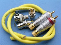
Btw,
this is the BNC kit,
This is a very high quality ENC socket.
middlePTFE diaelectric, Beryllium copper shield. soft high purity copper gold plated central pins.
Outside is nickel plated bell brass.
Every kit will contain two sets.
two same quality BNC to RCA adapter.
Two female BNC sockets will be follow with this kits that diyers can directly exchange the RCA socket from the back of the DAC to BNC. BNC had more band-width.
one more pair silverlink USA RCA socket will follow that can diyer another digital cables.
pls see the photos. Audionote RCA sockets also OEM by this factory.
Very thick gold plated parts.
every digital kit will follow with 1.5m belden 1505a 3Ghz digital cable.
thx
thomas
dear quantran,
diyers opinions is very important. Yours too! Otherwise too many different brand but similar chips in the world. We cannot try & test everyone of them that will provide better performance in our kit. Doyers opinions provide space to upgrade the kit.
thx of all.
Btw,
this is the BNC kit,
This is a very high quality ENC socket.
middlePTFE diaelectric, Beryllium copper shield. soft high purity copper gold plated central pins.
Outside is nickel plated bell brass.
Every kit will contain two sets.
two same quality BNC to RCA adapter.
Two female BNC sockets will be follow with this kits that diyers can directly exchange the RCA socket from the back of the DAC to BNC. BNC had more band-width.
one more pair silverlink USA RCA socket will follow that can diyer another digital cables.
pls see the photos. Audionote RCA sockets also OEM by this factory.
Very thick gold plated parts.
every digital kit will follow with 1.5m belden 1505a 3Ghz digital cable.
thx
thomas
Attachments
Hi Thomas,
Whilst I am awaiting those other parts from you, can you post more instructions on the tube buffer and the transformers please?
I would like:
- Transformer colour codes (I have the 230V ones)
- Choke or battery bia connections
- Configuration of tubes
Many thanks,
Jonathan
Whilst I am awaiting those other parts from you, can you post more instructions on the tube buffer and the transformers please?
I would like:
- Transformer colour codes (I have the 230V ones)
- Choke or battery bia connections
- Configuration of tubes
Many thanks,
Jonathan
- Status
- This old topic is closed. If you want to reopen this topic, contact a moderator using the "Report Post" button.
- Home
- Vendor's Bazaar
- Ultimate Twin TDA1541a Non-oversampling DAC with tube buffer & reclock set.......