Hi folks,
The french forum www.homecinema-fr.com/forum has been upgraded to phpBB v3... Arf, all is a mess, so direct links are probably down or wrong.
It's not possible for now to give the new links, as the webmasters are still working.
Too bad we were not warned, so no personal backup is made
The french forum www.homecinema-fr.com/forum has been upgraded to phpBB v3... Arf, all is a mess, so direct links are probably down or wrong.
It's not possible for now to give the new links, as the webmasters are still working.
Too bad we were not warned, so no personal backup is made


Cheffs Soft V. 1.10 available .
Minor bug corrected and one remote function added
quoted from french forum
( for original post look at : EDIT du 26/5/8 - Version 1.10 )
ATmega64, displayCrystalFontz
ATmega128, display CrystalFontz Special Maousse
ATmega64, display Optrex Spécial Idéfixes et Psykok
Manu special edition
.Minor bug corrected and one remote function added
quoted from french forum
( for original post look at : EDIT du 26/5/8 - Version 1.10 )
ATmega64, displayCrystalFontz
ATmega128, display CrystalFontz Special Maousse
ATmega64, display Optrex Spécial Idéfixes et Psykok
Manu special edition
Evening All,
I am going to stick my neck out again. I do not have a Phillips type remote control so I do not have a lead on this:
Does the microcontroller system provide a balance control from either the input knob or from the remote control?
"But why a balance control," I hear you ask, aghast? I use my speakers in two positions - one which is wife friendly and close to the walls, and one which is hi-fi friendly, right out in the room - and for reasons I cannot entirely fathom, the balance setting between both speaker positions is VERY different.
If a balance function is not currently available, would anybody be able to code it for me, at least from input knob. I could possibly do the control code for varying the balance between the channels, but I would not be able to work out how to get the LCD to say "Balance" or, even worse, how to get the remote to provide a balance function before I have one foot in the grave. But if no-one can help, I can understand because it would be a huge task.
With thanks,
George.
(I am currently organizing the purchase of parts, and am psyching myself up for the SMD soldering. I am going to try the "snack oven" method first.)
Oh, yes, just a point, the ATMEL ATMEGA128-16AU is pin compatible with the PCB (I use it) and just needs a specific firmware.
Historically, this was for fixing a dead µC board
But now, the choice is yours (dépending on the components supplier) between the ATMEGA64-16AU and the ATMEGA128-16AU.
The hardest to solder is the µC chip. Just use a lot of SMD flux, and do not overheat.
BTW, remember that the µC is 5V CMOS, so watch out ESD, and DMM testings...
Dodgy jfets or the real McCoy?
Hi folks,
Unsure of the best place to put this post, but since "fun and success with the UGS" turns on those little critters, I thought good advice could be found here.
I have a selection of jfets: supposedly 2SJ109, 2SK389 and 2SK170. I watched the sad spectacle of the Group Buy of these little gems which turned out to be fakes in the Group Buys part of this bulletin board.
Let us presume that some of mine might be fakes, but at least semiconductor devices (the most likely would be the 2SK389 and 2SK170, because they are of untried Asian origin.) How might I test this? (Yes, I am a sucker for the current feel-good, Year of the Olympics, Era of the Powerful Tiger, Chinese aura.)
First I thought that I would need to identify the type of device: BJT, Jfet or Mosfet. (If I were to counterfeit something and label it a Jfet, the least I would do is put in a BJT so it provided some transistor functions. If it was just an empty piece of plastic or a piece of plastic with a wire in it, my counterfeiting business would not last long.)
At first, I guess I need to work out whether the item is roughly the same general type as it labelled (N-channel or P-channel jfet with the same pinouts as the originals).
I thought that if I used a circuit as in Figure 20 of Nelson's DIYOpamp article, and tested a jfet, I would expect results similar to the diagram - about 2 mA current flow and a voltage of about 0.3V across the resistor. But what would I see if the device were an NPN BJT or N-ch MOSFET instead - a much lower current flow?
What would be my next step - to change the resistor by a small increment and recheck the result - or is correct function in the Figure 20 circuit enough to think that the components are the real McCoy?
And if that test looks right, then should I just I pop them into a UGS-like circuit, and if beautiful music comes out rather than smoke, I guess that the voltage capabilities are right.
Of course, I do not want to destroy any REAL Toshiba devices in my testing, and it all has to be done with nothing more than a multimeter.
I am going to stop there rather than demonstrate my ignorance any further. If I am terribly wrong, I hope I have provided you with some wholesome entertainment, or at least a few .
Thanks for your thoughts.
(Sgt) Hans Georg Schultz
Hi folks,
Unsure of the best place to put this post, but since "fun and success with the UGS" turns on those little critters, I thought good advice could be found here.
I have a selection of jfets: supposedly 2SJ109, 2SK389 and 2SK170. I watched the sad spectacle of the Group Buy of these little gems which turned out to be fakes in the Group Buys part of this bulletin board.
Let us presume that some of mine might be fakes, but at least semiconductor devices (the most likely would be the 2SK389 and 2SK170, because they are of untried Asian origin.) How might I test this? (Yes, I am a sucker for the current feel-good, Year of the Olympics, Era of the Powerful Tiger, Chinese aura.)
First I thought that I would need to identify the type of device: BJT, Jfet or Mosfet. (If I were to counterfeit something and label it a Jfet, the least I would do is put in a BJT so it provided some transistor functions. If it was just an empty piece of plastic or a piece of plastic with a wire in it, my counterfeiting business would not last long.)
At first, I guess I need to work out whether the item is roughly the same general type as it labelled (N-channel or P-channel jfet with the same pinouts as the originals).
I thought that if I used a circuit as in Figure 20 of Nelson's DIYOpamp article, and tested a jfet, I would expect results similar to the diagram - about 2 mA current flow and a voltage of about 0.3V across the resistor. But what would I see if the device were an NPN BJT or N-ch MOSFET instead - a much lower current flow?
What would be my next step - to change the resistor by a small increment and recheck the result - or is correct function in the Figure 20 circuit enough to think that the components are the real McCoy?
And if that test looks right, then should I just I pop them into a UGS-like circuit, and if beautiful music comes out rather than smoke, I guess that the voltage capabilities are right.
Of course, I do not want to destroy any REAL Toshiba devices in my testing, and it all has to be done with nothing more than a multimeter.
I am going to stop there rather than demonstrate my ignorance any further. If I am terribly wrong, I hope I have provided you with some wholesome entertainment, or at least a few
.Thanks for your thoughts.
(Sgt) Hans Georg Schultz
DMM damage to chip
Back again
While I am typing, how can I cause damage with the Atmel chip using my DMM? Because if there is a way to do it, I will find it!
Regards,
George.
Maousse wrote:
BTW, remember that the µC is 5V CMOS, so watch out ESD, and DMM testings...
Back again
While I am typing, how can I cause damage with the Atmel chip using my DMM? Because if there is a way to do it, I will find it!
Regards,
George.
Juste because max voltage is something like 5.5V, and there is a 9V battery in your DMM
I soldered all µC of the first GB (on the french forum) and flashed them (so they were OK). In the µC I changed for the guys, there were two that were working before DMM continuity testings and died after DMM continuity testings.
I soldered all µC of the first GB (on the french forum) and flashed them (so they were OK). In the µC I changed for the guys, there were two that were working before DMM continuity testings and died after DMM continuity testings.
Manu said:Hi,
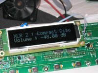
Here a little pic.
To give a concrete idea of size , I have put next to the display a box of famous Cachou Lajaunie
You certainly want to see it "in action" but unfortunately my uC board is actually configured for Christalfuntz LCD (Backlight current and connections).
As soon as I find the time to make the changes I ll post a new pic.
Manu
Manu's optrex display
The contrast adjustment is a little critical.
I need -700mV for the best result.
GeorgeBoles said:I have a selection of jfets: supposedly 2SJ109, 2SK389 and 2SK170. ...
Let us presume that some of mine might be fakes, but at least semiconductor devices (the most likely would be the 2SK389 and 2SK170, because they are of untried Asian origin.) How might I test this?
Just tie the supposed gates to the supposed sources.
Take a 9V battery cell.
Join the gate/source nodal point to the "minus" of the battery (for NJfets) or to the "plus" of the battery (for PJfets)
Take a DMM in AmpMeter position (200mA)
Connect one probe of the DMM to the other pole of the battery.
And connect the other probe of the DMM to the supposed drain of the JFet
Then you should read on the DMM the Idss parameter of the JFet (take the absolute value of the value).
Just check if this value matches the datasheet classification (wrt GR/BL/V), and you're done.
If it doesn't match, no need to worry about what it really is, drop it to the dumpster
If it does match, you most likely have a right fet.
Then you could use Nelson's fig20 schematic using two different resistors (use your 9V battery, and invert polarities for PFets) and compute the transconductance of the fet :
First resistor gives V1 on the first resistor R1
Second one gives V2 on R2
then gm=((V1/R1)-(V2/R2))/(V1-V2)
and compare to datasheet values.
Don't you use the onboard contrast adjustment (I see a little trimmer on the photograph) ?joho said:The contrast adjustment is a little critical.
I need -700mV for the best result.
CheffDeGaar said:
Don't you use the onboard contrast adjustment (I see a little trimmer on the photograph) ?
Hi cheff,
It's a long time ago on this forum isn't it?
Yes, for the moment i use 2 trimmers for the display. I forgot to order the integrated circuit. In fact when i put the contrast regulation almost to ground it looks good but you can see the square blocks behind the characters. So i add a negative supply to make the contrast regulation a little negative. But as i've sad, there is a very small "soft spot".
B.t.w. i download you're latest software version for the optrex variant. When i turn the controller off there is some message in a strange language. What does it mean?
Gr.
Johan
- Home
- Amplifiers
- Pass Labs
- UGS adventures