Just to write some boring information for the readers.
The famous R1, which was replaced in my case using a choke.
As we know, i had a high B+, so a resisitor/s was fitted from the centre tap of the secondary to ground.
I was 'playing' with values to get just over 320v.
I am happy to say that my resistors are now 150 ohm + 330 ohm = 103 ohm, giving me a B+ of 322v.
As for the voltage across R1 (103 ohms) we have 22.16 v.a.c.
Yes Francois, you were so close with your recommended 100 ohms.
So i think it's 22.16v X 22.16v ÷ 103R = 4.78 watts
Out of curiosity, how do i work out the wattage per resistor?
Based on the B+ 322v i measured these voltages: -
V102 Cathode = 11.07v - therefore = 0.034 A (11.07v÷ 322v = A)
V101 Cathode = 10.86v - " " = 0.034 A
V202 Cathode = 10.83v - " " = 0.034 A
V201 Cathode = 11.17v - " " = 0.035 A
Also measured (for power dissipation): -
R117 / V102 pin 9 = 319.5v (319.5v - 11.07v = 308.43) X 0.034 = 10.48 W
R113 / V101 pin 9 = 319.7v (319.7v - 10.86v = 308.84) X 0.034 = 10.50 W
R217 / V202 pin 9 = 319.5v (319.5v - 10.83v = 308.67) X 0.034 = 10.50 W
R213 / V201 pin 9 = 319.3v (319.3V - 11.17v = 308.13) X 0.035 = 10.79 W
Yes Francois, you were so close with your recommended 100 ohms.
So i think it's 22.16v X 22.16v ÷ 103R = 4.78 watts
Out of curiosity, how do i work out the wattage per resistor?
 Lucky guess.
Since both resistors have the same 22.16 V across them you can simply use the same formula with the individual resistor values as divisor. I.e. 22.16 x 22.16 ÷ 150R = 3.274 Watts.
When you are ready please l us know how it sounds, and perhaps a picture or two of what your final product looks like.
Hello calpe,
... for the current flow (Ohm's law)
V102 => 11.07 V / 300 Ω = 0.0369 A
V101 => 10.86 V / 300 Ω = 0.0362 A
V202 => 10.83 V / 300 Ω = 0.0361 A
V201 => 11.17 V / 300 Ω = 0.0372 A
... and for power dissipation
V102 => (322 - 11.07) * 0.0369 = 11.47 W
V101 => (322 - 10.86) * 0.0362 = 11.26 W
V202 => (322 - 10.83) * 0.0361 = 11.23 W
V201 => (322 - 11.17) * 0.0372 = 11.56 W
The current flow can be determined by measuring the voltage across the relevant resistor R113/R117 (100 ohms).
In each case the measuring probe at the ends of the resistor.
Best regards
Unfortunately, an incorrect value was used in the calculation. For the total dissipation, the value of the resistance of R112/R116 (300 ohms) must be used.Based on the B+ 322v i measured these voltages: -
V102 Cathode = 11.07v - therefore = 0.034 A (11.07v÷ 322v = A)
V101 Cathode = 10.86v - " " = 0.034 A
V202 Cathode = 10.83v - " " = 0.034 A
V201 Cathode = 11.17v - " " = 0.035 A
... for the current flow (Ohm's law)
V102 => 11.07 V / 300 Ω = 0.0369 A
V101 => 10.86 V / 300 Ω = 0.0362 A
V202 => 10.83 V / 300 Ω = 0.0361 A
V201 => 11.17 V / 300 Ω = 0.0372 A
... and for power dissipation
V102 => (322 - 11.07) * 0.0369 = 11.47 W
V101 => (322 - 10.86) * 0.0362 = 11.26 W
V202 => (322 - 10.83) * 0.0361 = 11.23 W
V201 => (322 - 11.17) * 0.0372 = 11.56 W
For the calculation of the dissipation of g2 (max. 2.2W) the value at pin 9 is necessary, but also the current flow at this point.Also measured (for power dissipation): -
R117 / V102 pin 9 = 319.5v (319.5v - 11.07v = 308.43) X 0.034 = 10.48 W
R113 / V101 pin 9 = 319.7v (319.7v - 10.86v = 308.84) X 0.034 = 10.50 W
R217 / V202 pin 9 = 319.5v (319.5v - 10.83v = 308.67) X 0.034 = 10.50 W
R213 / V201 pin 9 = 319.3v (319.3V - 11.17v = 308.13) X 0.035 = 10.79 W
The current flow can be determined by measuring the voltage across the relevant resistor R113/R117 (100 ohms).
In each case the measuring probe at the ends of the resistor.
Best regards
Since both resistors have the same 22.16 V across them you can simply use the same formula with the individual resistor values as divisor. I.e. 22.16 x 22.16 ÷ 150R = 3.274 Watts.
150 & 330 ohm 10W Resistors, I had to order via my nearest component shop in Algeciras (Spain), 20 min drive. Should be here by Saturday.When you are ready please l us know how it sounds, and perhaps a picture or two of what your final product looks like.
Once fitted etc., I'll happily post finished pictures
Trust me to balls up the calculations, thanks for the corrections.Hello calpe,
For the calculation of the dissipation of g2 (max. 2.2W) the value at pin 9 is necessary, but also the current flow at this point.
The current flow can be determined by measuring the voltage across the relevant resistor R113/R117 (100 ohms).
In each case the measuring probe at the ends of the resistor.
Best regards
I will check the other voltages across R113, 117, 213 and R217 as soon as i can.
From post #566 would i be correct in saying: -
P = V x I (voltage dropped across screen X Screen current)
V102
0.49v (across R117) ÷ 100 (R117) = 0.0049A (4.9mA)
319 (+V on pin 9 V102) X 0.0049 = 1.56 watts
V101
0.48v ÷ 100R = 0.0048A
319v X 0.0048A = 1.53 watts
V202
0.49v ÷ 100R = 0.0049A
319v X 0.0049A = 1.56 watts
V201
0.48v ÷ 100R = 0.0048A
319v X 0.0048A = 1.53 watts
How does this appear?
Close, but you need to subtract the cathode voltage from the screen grid voltage before multiplying by the current, for example:
V102
0.49v (across R117) ÷ 100 (R117) = 0.0049A (4.9mA)
319-11.07(+V on pin 9 V102 - V102 Cathode voltage) X 0.0049 ~ 1.51 watts
V102
0.49v (across R117) ÷ 100 (R117) = 0.0049A (4.9mA)
319-11.07(+V on pin 9 V102 - V102 Cathode voltage) X 0.0049 ~ 1.51 watts
Thank you kindly for the corrections. Trust me!Close, but you need to subtract the cathode voltage from the screen grid voltage before multiplying by the current, for example:
V102
0.49v (across R117) ÷ 100 (R117) = 0.0049A (4.9mA)
319-11.07(+V on pin 9 V102 - V102 Cathode voltage) X 0.0049 ~ 1.51 watts
What does the 1.51 watts indicate?
I've looked at the technical sheet of the Sovtek EL84, didn't see anything.
Last edited:
I've looked at the technical sheet of the Sovtek EL84, didn't see anything.
Datasheet here (P = power, a = anode, g2 = grid2)
Pg2, maximum screen grid power dissipation. You are way below 2.2W, as shown by @stonegreen above.Thank you kindly for the corrections. Trust me!
What does the 1.51 watts indicate?
I've looked at the technical sheet of the Sovtek EL84, didn't see anything.
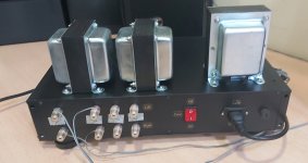
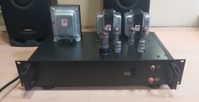
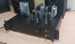
Images of my nearly complete build.
Just a few labels and tidying up of the inside cabling.
Otherwise, the sound is superb.
Many thanks to you all, for your patience and assistance.
Just a few labels and tidying up of the inside cabling.
Otherwise, the sound is superb.
Many thanks to you all, for your patience and assistance.
Attachments
- Home
- Amplifiers
- Tubes / Valves
- Tubelab SPP first timer build