Good news, @grataku. Very nice work. Those Hashimoto’s must have hurt the piggybank, but I’m sure they make beautiful music.
I’m curious how the output transformers and choke are fixed to the top plate - looks like they just slide into carefully cut holes.
I’m curious how the output transformers and choke are fixed to the top plate - looks like they just slide into carefully cut holes.

Thanks Francois! All bought on ebay from Japan. Iron is the typical japanese made with obsessive attention to detail and comes with a thin label plate that you see here and you can use that directly to mark mounting holes 4xM4 + central terminal hole on the pvc adesive cover of the Al plate. I have a crappy drill press and I bought a nice 35mm hole cutter from McMaster that cuts that big hole like butter. The plate is 3/16 6061 Al cut to size from onlinemetals. The power transformer I do with a jigsaw+ Al blade and file. The measurements are all given on Hashimoto's datasheet. My skills, especially woodworking, leave a lot to be desired so I find that formula of wood box with aluminum corners and center brace that is screwed and glued makes for a very sturdy enclosure. I tried 1/8 plate but the transformers are heavy and the flex is excessive. 3/16 is super solid. The bonus with 3/16 Al is that it acts as heatsink and distributes the heat away from critical components.
Hi all, wanted to share my new completed Tubelab SPP. I relied quite a bit on the Wall of Sound articles - thanks Steve! Two switchable inputs, feedback on/off switch, and two mode switches (one for each channel) to choose triode, pentode or ultra linear. I also used Steve’s design for bias adjustment. Works perfectly!


Yes, love the engraving too. A company I used to work for threw their old mechanical hand-operated engraver away. I wish I'd been there to catch it.
Be careful of the switches in the high voltage DC. They are often rated for lower DC voltage than they are AC.
I can't take credit for the bias circuit. Shannon Parks at DIYTube.com used this trick on his Dynaclone boards, unfortunately no longer available.
Be careful of the switches in the high voltage DC. They are often rated for lower DC voltage than they are AC.
I can't take credit for the bias circuit. Shannon Parks at DIYTube.com used this trick on his Dynaclone boards, unfortunately no longer available.
Thanks. I have a homemade CNC machine that I used for the engraving. For my last project (Tubelab TSE), I cut all the holes and engraved the top plate similar to this project. That was a few years ago. For this project, I discovered Xometry, through which I was able to order the top plate with all holes water-jet cut for only $20 more than what the raw aluminum stock would have cost from a local metal supplier. Xometry’s cost is reasonable for 2D cutting, but engraving was a bit more, so I still did that part myself.
The mode switches are rated for 1,000 Vrms dielectric strength. I think they’ll be okay so long as they’re not switched while powered. I put the switches behind the transformers to prevent accidental switching when the amp is in use. That said, I’ll definitely keep an eye on them.
For the bias adjustment, I might try reworking a portion of it. With the pot turned down to no resistance, I’m only able to get 34.2 mV on average. I’d like the option of getting it to 40mV (not that I’d keep it there). I’ll check them again after a few hours of burn in.
@huggygood, thanks!
@Francois G, I used edcor transformers. The motor run cap is 100uf Temco. I removed the labeling and gave it a brushed finish.
@Francois G, I used edcor transformers. The motor run cap is 100uf Temco. I removed the labeling and gave it a brushed finish.

A little report on my swapping the 0.1uF caps from the default Illinois Capacitor 0.1uF to the equivalent white mundorf paper oil (the ones that Skunky uses).
The differences are significant! I had to go -3dB attenuation on the horn and lower the previous listening volume by another 3dB. Seems the IC have, at a minimum, a higher insertion loss and are rolled off on the high freq. This should definitely be measurable. The amp has gone from a guitar amp sound, sweet & colored and a little rolled off to clearer, sharper with enhanced high freq and stereo image.
I am curious what are people using for these caps?
These is what I am using.
https://www.madisoundspeakerstore.com/mundorf-mcap-evo-oil-caps/mundorf-0.1mfd-evo-oil-capacitor/
https://www.madisoundspeakerstore.com/mundorf-mcap-evo-oil-caps/mundorf-0.1mfd-evo-oil-capacitor/
Stumped and need help.
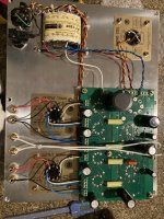
Upon completion all voltages checked out but with full complement of tubes, fuses blow. Has to be the way I've wired the Hammond 1650R output transformers https://www.hammfg.com/files/parts/pdf/1650R.pdf to the 16 terminals on the board. I removed the board and sent it off to a friend with more smarts and better test gear and the board takes voltage for an extended period and checks out fine. Here is the way I have it wired looking at the bottom of the board of course

Upon completion all voltages checked out but with full complement of tubes, fuses blow. Has to be the way I've wired the Hammond 1650R output transformers https://www.hammfg.com/files/parts/pdf/1650R.pdf to the 16 terminals on the board. I removed the board and sent it off to a friend with more smarts and better test gear and the board takes voltage for an extended period and checks out fine. Here is the way I have it wired looking at the bottom of the board of course
@BillEpstein,
Could you provide a bit more background? What output tubes are you using? Why are you using a 100W/5K output transformer for a circuit that outputs <20 watts and assuming you are using EL84 tubes you need an ~8K primary impedance. (Sorry if I missed this in earlier posts).
What speaker load are you wiring? I assume you looked at the schematic when you wired it up. I have not checked/looked at the schematic compared to what you have wired, but I suggest you draw a diagram of the 1650R wire colors with the speaker impedance you are targeting, and then lable each endpoint with the terminal lables Tubelab used on the PCB.
Last edited:
Oops! I relied on my memory and old notes. The OPTs are 1650FA https://www.hammfg.com/files/parts/pdf/1650FA.pdf
Tubes are EL-84.
Tubes are EL-84.
- Home
- Amplifiers
- Tubes / Valves
- Tubelab SPP first timer build