mind if i ask that, what will this values work for ? varying them will bring what difference ?You can use there:
103, 203, 223, 333, 473, 683, 823, 104, 154, 224, 274, 334, 474, and 1uf....even bigger will work there.
regards,
Carlos
well... hi alex ! first time we talk.... well.... more like writing X.xHi guitar69 ,
Have you built ever an diy audio amplifier ? If you are at the first amplifier just take a breake , becouse you have solder iron damaged and think , this amplifier will work , with or without 680 pF capacitor !!! so just se PCB in attachment
Regards Alex.
yeah.... this i not my first time, first time was a IC amp circuit.. so not difficult, but not the main point X.x
well..... i know the amp will work with/without it, but i want perfection
(not exactly perfect).... well... i mean same as it designed by the designer (carlos....... DESTROYER )
thanks for the attachment, i saw it. are you preparing your 'gift' gun/shooter, aiming for me ? carlos said so X.x
well.... i'm NOT finding people to scold, just love to make things correct in their way ^^ (this case, it was DX's way)
They are bypass capacitors...that other one you have asked
They are there to provide a low impedance patch to oscillations travel to ground.... but really, you will not have oscilations..so...no problems having or not having these capacitors..they are there "just in case"
What about to post less questions and to stop to search for differences and build the unit...you are giving me a lot of work man...give uncle charlie a break..i am old and i can have a heart attack.")
regards,
Carlos
They are there to provide a low impedance patch to oscillations travel to ground.... but really, you will not have oscilations..so...no problems having or not having these capacitors..they are there "just in case"
What about to post less questions and to stop to search for differences and build the unit...you are giving me a lot of work man...give uncle charlie a break..i am old and i can have a heart attack.
regards,
Carlos
ah.... sorry to bother you, uncle... but i think this is quite a big different connection between sketch and schematic...
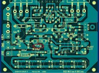
As attached picture, i have point out a resistor (R10) which have 2k7 ohm, is connected wrongly and the blue end terminal was connected to positive side of output condenser(C3).
Another doubt, is what i ask previously, is should the "A" and "A" connected ?
As attached picture, i have point out a resistor (R10) which have 2k7 ohm, is connected wrongly and the blue end terminal was connected to positive side of output condenser(C3).
Another doubt, is what i ask previously, is should the "A" and "A" connected ?
Attachments
Thanks alot, Alex... sorry for the trouble, anyway i couldn't find any other dissimilar ^^
I might become the one in QC department ! well.... inherent those QC quality from my mom... ( she was food specialist, work at food processing quality check)
Anyway, its late here.. going to sleep.... next morning going to rush out and get my new tool SOLDER IRON !!!! and begin my project... too much delay ! dunno will spend how much time to complete it !
hm........ dear tekko, there is 2 ways in life to success ! (applies in most thing)
1) read alot of things, know theory, import knowledge, then operation last (your way), also (modern way, eg. go to college learn alot, go to board international university,etc)
2) learn through the hard way : learn things by doing it alot, learn by the side, by yourself. Practice make perfects. (Old style carpenter doesn't teach their apprentice, just order them to do what, learn yourself what to do, by how and why)
Me myself is comprise of 2, do any of them whenever i have chances, therefore i come across this, so i'm building it without backing off (not the slightest chance of thought)
uncle, i'm scratching the copper board ! only manage to finish my power supply unit section.
**By the way, i'm using a nail polisher and a Phillip screwdriver(old one) to scrap the board, instead of steel ruler ( i don't have any at my house) ******
Going to make power supply section + 2-channel dx-trust into a single 20cm X 30cm board !
I'm designing my board (alex's sketch component size are alot different with mine) on the half way...
But i think it would take a few days to complete, a long job ! want me to give you a photo of my power section ?
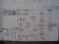
hehe, uncle, i'm using those time between do make my sketch by using pencil , based on my components and dimension.
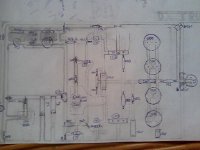
Although its not small, going to make it more compact (current size: 19cm x 12cm), because some space reservation are too big. The sketch only missing a input connection (left bottom, disconnected portion), a wire (connection of points "A"), and 4 x 7.5pf capacitor.
Will begin the etching (well...... i use scrapper, not chemical) on my board today, continue by tmrw, hope i can finish it by tmrw !
If you notice in the picture, there is a big spaces in the far left (middle), wanted to put some labeling in there. (eg.: left/right channel, dx trust, etc)
Dotted line are indicating the variable resistor and heat sink.
I just noticed left side about 5mm is not in the picture......
Is this the progress you wish to see ? (or you think i'm a slowpoke or a sloth)
Attachments
Edited new Sketch
I have attached another sketch, which is almost same as previous, but it is revised.
Some mistake in the circuit have cancelled and re-do, added information such as base, collector, emitter and polarity.
I'm thinking to put in a RCA receptor for the input only, to each channel.
Then at the power section, the lower part quite empty, so i'm thinking to put a 2 RCA receptor and a circuit into a TRS 3.5mm (computer plug), this makes the input flexible of RCA and TRS connection.
I will also port (by wires) the output to the lower part also, make a clipping stands and RCA output for 2 separate channel. This also make flexible of RCA and bare wires connection(clipping it).
Attachments
- Status
- This old topic is closed. If you want to reopen this topic, contact a moderator using the "Report Post" button.
- Home
- Amplifiers
- Solid State
- Trust, the most delicious Dx Amplifier