Great! It seems that you 'll end this design soon Frex.
BTW, apart from the preview manual you plan, a detailed BOM is necessary...
P.S. I would like to express my deepest condolences for the deaths of the people during the attacks in Paris.
BTW, apart from the preview manual you plan, a detailed BOM is necessary...
P.S. I would like to express my deepest condolences for the deaths of the people during the attacks in Paris.
Last edited:
Hi Frex,
Really amazing, I'm just asking myself if I will have the capability to solder all these SMD parts...
Jean Claude
Really amazing, I'm just asking myself if I will have the capability to solder all these SMD parts...
Jean Claude
Hello all,
First,
Jaac, Jean-Claude, Spirtos, Prasimix, Turbon and jvhb thank you for your compliments.
Spirtos, of course i will publish a complete bom. It already exist, but i need to complete and correct some little things.
I have do much job to give far all parts a vendor (mainly from Mouser) with vendor ref and price.
I would be easy to to get parts using importing this list.
For now, this is not a priority, but i keep it in mind.
Jcga don't be scared, only two parts require good soldering skills ; the TQFP144 and the MSOP8 thermal sensor.
If you have ; light (much) , magnifying glasses , good soldering iron, and of course not shaking hands
(I strongly recommend to NOT drink coffee before !).
The difficulty is to align all pins on PCB pads, if you have done that (using a small adhesive tape to fi it),
you can solder all 144 pins using tin with solder flux.
Many video on Youtube describe how to proceed.
I will come back very soon with projects news.
Regards.
Frex
Everything you mentioned is correct Frex. A detailed BOM with vendor references is better, and it is not major priority for now. I am just wondering what would be the components' cost.
Hello,
These days i worked on various things about the project.
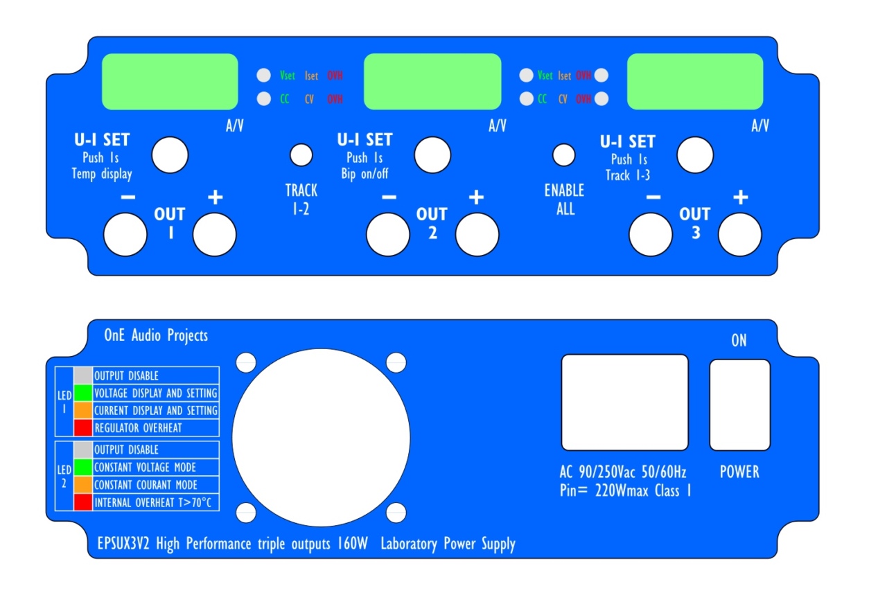
First, finish the front panels Lexans design, now near to be ready to send
for manufacturing. I hope to send them them next week (that would be a very nice Christmas gift for me !).
The lexans will look like this :
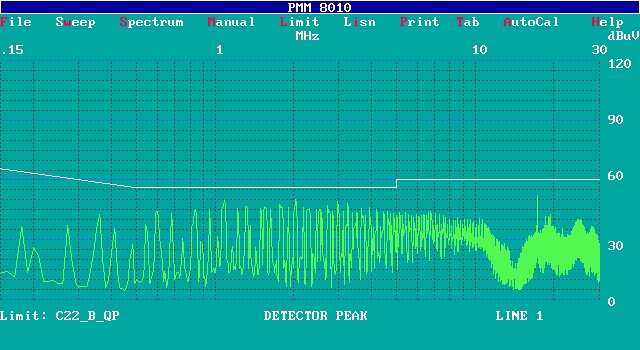
Second, i have made also some EMC testing, in particular conducted emission on power cord.
The PSU pass successfully class B level (the most severe level).
To do that, i've need to add a small shielding screen using a piece of PCB to avoid coupling between
PFC inductor and the input main connector wires.
The result below, at full load (3x18V-3A // Po= 160W) on Line 1.
And, i have also made a lot of output noise measurements and optimizations.
In my first tests, i have noticed output noise level about 1mVrms.
That's not bad, but LT3081 can normally perform much better performance.
After some investigation, the noise source was the DAC noise (MCP4802).
The DAC add a large amount of noise, in particular a low frequency.
To correct that and because my target is to get higher performance possible,
i've made some modifications on EPSUX3REGV2 regulators boards, and now
i get about 40µV rms for 5Hz to 20MHz bandwidth and less than 20µV in audio band (10Hz-100kHz).
All of these modifications are only parts values change.
The PSU work very well, and i have already done many measurements ;
Output voltage rise and fall time at light and full load,
Capacitive output response,
Noise test in full band and audio band.
Much more are in progress....
Project to follow ...
Frex
These days i worked on various things about the project.
First, finish the front panels Lexans design, now near to be ready to send
for manufacturing. I hope to send them them next week (that would be a very nice Christmas gift for me !).
The lexans will look like this :
Second, i have made also some EMC testing, in particular conducted emission on power cord.
The PSU pass successfully class B level (the most severe level).
To do that, i've need to add a small shielding screen using a piece of PCB to avoid coupling between
PFC inductor and the input main connector wires.
The result below, at full load (3x18V-3A // Po= 160W) on Line 1.
And, i have also made a lot of output noise measurements and optimizations.
In my first tests, i have noticed output noise level about 1mVrms.
That's not bad, but LT3081 can normally perform much better performance.
After some investigation, the noise source was the DAC noise (MCP4802).
The DAC add a large amount of noise, in particular a low frequency.
To correct that and because my target is to get higher performance possible,
i've made some modifications on EPSUX3REGV2 regulators boards, and now
i get about 40µV rms for 5Hz to 20MHz bandwidth and less than 20µV in audio band (10Hz-100kHz).
All of these modifications are only parts values change.
The PSU work very well, and i have already done many measurements ;
Output voltage rise and fall time at light and full load,
Capacitive output response,
Noise test in full band and audio band.
Much more are in progress....
Project to follow ...
Frex
There is a little error with English in the back side: it should be "Constant current mode" instead of "Constant courant mode"
Hello,
THank you jcga.
Happy to see that French DIYer is in !
For now there is 9 pre-order on wiki list. That is a good start!
Frex
THank you jcga.
Happy to see that French DIYer is in !
For now there is 9 pre-order on wiki list. That is a good start!
Frex
Hi FRex,
I followed your presentation and as I said before it's very impressive, the ratio performance / size is unseen on the market.
I probably missed something but I don't see an individual output ON/OFF switch
JC
I followed your presentation and as I said before it's very impressive, the ratio performance / size is unseen on the market.
I probably missed something but I don't see an individual output ON/OFF switch
JC
Hello JC,
Thank you very much.
You have not missed anything, there is no individual on/off switch.
The right toggle switch allow to turn off all three outputs simultaneously,
so if you need to set only one output to zero you will need to disconnect
manually this output (removing the banana).
Nevertheless, if this functionality seems essential for many people, it is possible to add this only by modifying software in CPLD.
Individual on/off could be done for exemple by pressing 2 seconds the encoder push-button of the channel we want to switch on or off.
Many things are possible ! 🙂
Regards.
Frex
Hello all,
Wiki pages are down, so if you want to be added to pre-order list please send me a pm and I will add you until wiki become available again.
Regards.
Frex
Wiki pages are down, so if you want to be added to pre-order list please send me a pm and I will add you until wiki become available again.
Regards.
Frex
Hello Frex!
Nice design, the PFC+LLC step is very advanced. Clever way of generating -VBIAS2 on combo board. And the LT3081 is ofcourse the "star of the show". But why the simple 8-bit MCP4802 and not the 12-bit MCP4822?
Looking at your latest video, I'm a bit concerned regarding the measured and displayed voltages. Initially ch1 was stable at 5.99, then after you pushed knob on ch3 it started jumping around 6.00-6.02. Looking at the circuit, I don't understand what the 100 ohm R32 and R36 do. Don't they decrease performance of MCP3202? Removing them would improve input impedance.
Looking in the manual, I see no description of how to calibrate the channels. When in tracking mode, it is very important the channels are calibrated/synchronized.
Hello PH01,
Thank you for comments, you seem that you have look the design deeply, it's a good thing !
You ask why i use 8 bits DAC but 12bits ADC.
8 bits for the 0 to 20V output scale get here 100mV resolution.
Using 12 bits ADC for voltage measurements give 10mV resolution.
IMHO, 100mV for output voltage control is sufficient (but i agree that is personal and linked to my own needs and uses).
I use 12 bits ADC to improve resolution of measurement when i want to set voltage
below to 10V.
So, when voltage is below 10V, the last digits of the display correspond to the LSB of
the 12 bits ADC.
But don't worry, if using 12 bits control is very important for your need, the MCP4802 dual 8 bits DAC can be replaced by the 10 or 12 bits version (4812-4822) without any hardware modification. You will only need to change the CPLD code in order to work with (the full software CPLD code of the project will be provided to builders).
The resistor R32/R36 in conjunction with C40/C41 allow low-pass filtering at ADC inputs, but also allow to get very low HF input impedance. The series resistors are needed also to decouple the OPAMP outputs to the C40/C41 filtering caps and avoid it to become unstable. So, the 100 Ohms resistors (R32/R36) doesn't degrade ADC performance, even in DC. In fact, ADC bias current is 1nA typical, creating about 100nV offset at input --> negligible compared to LSB value.
There is no calibration needed (and planned) on the PSU.
In practical use, when you use the three channels in parallel mode, and if you have use equal cable length, the output current tending to naturally balance.
I've tested the parallel mode very deeply, and without any precision resistors in signal chain (like 0.1%) and any calibration i can get 9A without problem and current sharing is very good. The 100mOhms series resistances that you can find on all LT3081 regulators help much to achieve that.
Regards.
FRex
There is no calibration needed (and planned) on the PSU.
Hm, from my experience (and some other builders, not to mention Keysight and similar commercial solutions) it's correct as long as you stay with 100mV resolution. But, when you go down to e.g. 10mV step (not to mentioned 1mV that can offer high performance laboratory PSUs) calibration is required (or some additional way of reference offset adjustment is required). Did you try that with 10mV resolution? I usually got up to 30mV difference. Ok, that is with the 3rd class multimeter 🙂, but still when you make a correction MCU is faithfully follow it.
Hello prasimix,
You're right, if you target 12 bits "precision" NOT resolution, you could need calibration to get this.
It's for this reason that i considering that 8 bits control will be sufficient with voltage control.
And as you write, is that a 30mV difference (between reading and real voltage) is a concern for a lab PSU ?
Probably not in most case. 🙂
Regards.
FRex.
(So, no doubt that i'm open suggestions, no doubt too that all of these points will turn in my head.
So calibration implementation in CPLD could be done, but need space and time. I will see..)
Hello prasimix,
You're right, if you target 12 bits "precision" NOT resolution, you could need calibration to get this.
It's for this reason that i considering that 8 bits control will be sufficient with voltage control.
And as you write, is that a 30mV difference (between reading and real voltage) is a concern for a lab PSU ?
Probably not in most case. 🙂
Regards.
FRex.
(So, no doubt that i'm open suggestions, no doubt too that all of these points will turn in my head.
So calibration implementation in CPLD could be done, but need space and time. I will see..)
I learned that e.g. 30mV for orthodox people could sound as true heresy if we mentioned "laboratory" word, but if we stick with "bench(top)" then everything goes smooth 🙂.
Anyway, one step at the time. I have no experience with CPLD but could imagine that is not so straightforward as C/C++ programming that you can do on MCUs such as PIC, AVR or ARM (not to mention so many libraries available in the open source community). Maybe that could be a logical step for the next version 3 (+ at least support for richer display). Keep up the good work

- Home
- Design & Build
- Equipment & Tools
- Triple outputs 160W Lab PSU -- EPSUX3 version 2 !