EPSUX3V2 all boards wired.
Hello all,
From my last post some work has been done.
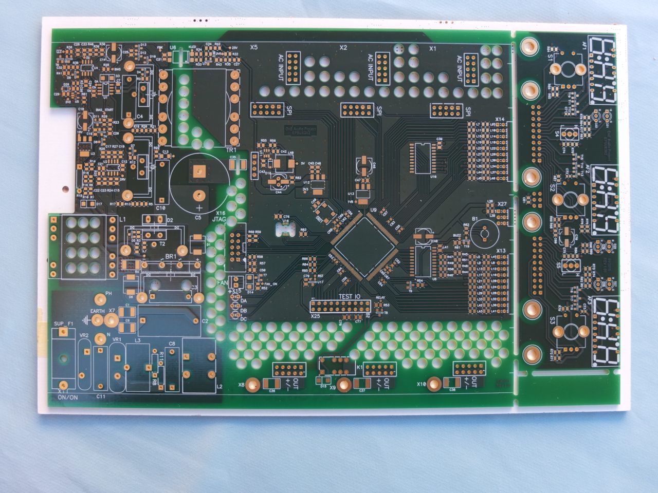
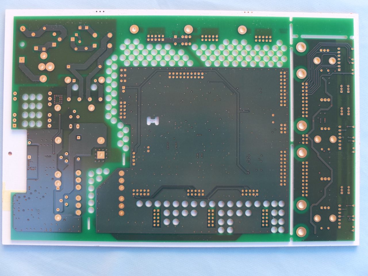
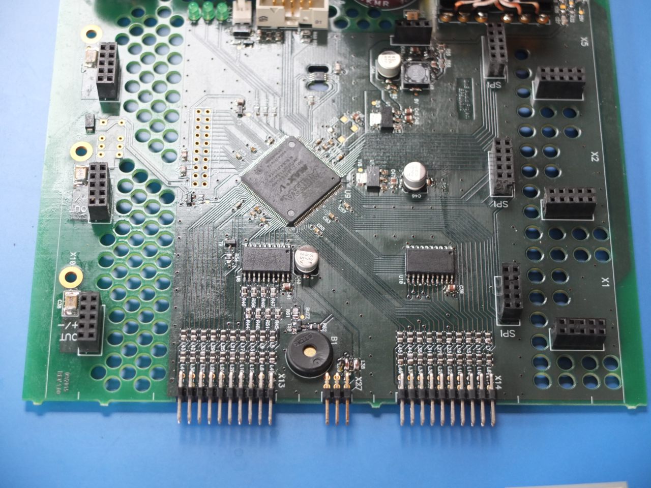
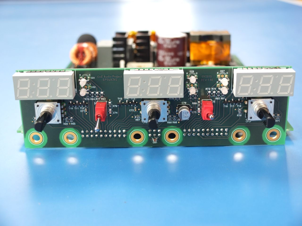
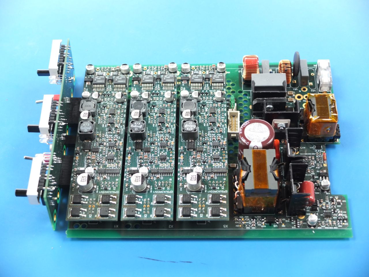
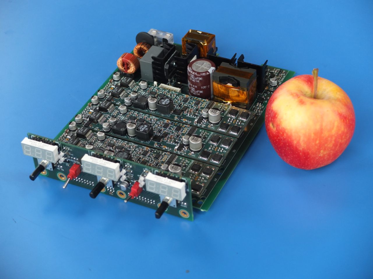
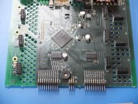
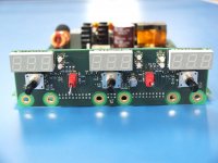
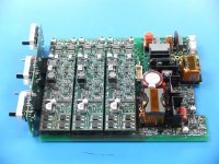
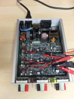
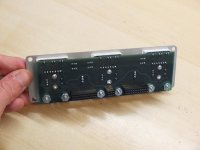
The two circuit board (main and front panel) has been fully wired, smd and through holes parts.
The magnetics parts has been also newly wound, and i wrote a full winding procedure for LLC transfomer and PFC inductor including many pictures.
I've also work on moving to Quartus II version allowing MAX V device i use in board.
Many tests are in progress. I 've started to supply the logics with extrenal PSU, and 5v/3v3 and 1.8V are ok. I've also tried to program the CPLD with a test software successfully. At this point i have seen a "fu..ing" pcb routing issue...
I've inverted the signals coming from the two right angle 20 pins connector of the front panel board...**** !
So, all pins coming directly to or from CPLD can be input or output as i program them inside. So, many ot them can stay in place with only CPLD software changes.
So, for others pins coming to HC540 buffers, i need to add many "on the fly" wires to route them in correct way. I think to do that nicely.
I need time to continue all tests that are very numerous here !
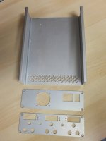
The mechanical has seriously progress too. All circuits boards fit very well in the enclosure, and i cut out prototypes panels in thick carton to check all holes placement before to machined the real aluminium panels.
")
Some pictures of the wired boards :


Some others pictures with circuits boards in the enclosure will be posted soon.
To follow...
Frex
Hello all,
From my last post some work has been done.
The two circuit board (main and front panel) has been fully wired, smd and through holes parts.
The magnetics parts has been also newly wound, and i wrote a full winding procedure for LLC transfomer and PFC inductor including many pictures.
I've also work on moving to Quartus II version allowing MAX V device i use in board.
Many tests are in progress. I 've started to supply the logics with extrenal PSU, and 5v/3v3 and 1.8V are ok. I've also tried to program the CPLD with a test software successfully. At this point i have seen a "fu..ing" pcb routing issue...
I've inverted the signals coming from the two right angle 20 pins connector of the front panel board...**** !
So, all pins coming directly to or from CPLD can be input or output as i program them inside. So, many ot them can stay in place with only CPLD software changes.
So, for others pins coming to HC540 buffers, i need to add many "on the fly" wires to route them in correct way. I think to do that nicely.
I need time to continue all tests that are very numerous here !
The mechanical has seriously progress too. All circuits boards fit very well in the enclosure, and i cut out prototypes panels in thick carton to check all holes placement before to machined the real aluminium panels.
Some pictures of the wired boards :
Some others pictures with circuits boards in the enclosure will be posted soon.
To follow...
Frex
Attachments

An externally hosted image should be here but it was not working when we last tested it.
Looks very good.

Hello prasimix,
Yes, the step-down pre-regulator follow very well the output setted voltage+margin (~2V). The scheme is same as described in LT note and work very well.
Frex
I tested it also and in my case there is a ~0.9V difference on 0-40V scale (2.3V on Vout=0V and 1.4V on Vout=40V). Strange
.EPSUX3V2 - video of first tests and mechanical preview.
Hello ,
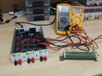
Some tests has been made on the main PCB, and all work as expected for now.
The PFC gave the 400V awaited and the LLC start well and i get 25V on each outputs. I don't have already done extensive measurements, but i'll probably do that next week.
I can read and program the MAX V CPLD, and i made a test program to check all I/O of the PLD before to try the real CPLD program.
The test mode allow to check each displays,leds, rotary encoders and their push-button,toggle switch,fan control, buzzer, and all others digital I/O.
If you are curious and want to show how it work, you can look this small movie where i describe the test mode and the mechanical integration.
The movie is HERE :EPSUX3v2 test preview
I work now on testing with real CPLD program.
To follow....
Regards.
Frex
(Prasimix, you problem come maybe because you use it in wider voltage range. If you want, send me
your schematic of the regulator and i will look).
Hello ,
Some tests has been made on the main PCB, and all work as expected for now.
The PFC gave the 400V awaited and the LLC start well and i get 25V on each outputs. I don't have already done extensive measurements, but i'll probably do that next week.
I can read and program the MAX V CPLD, and i made a test program to check all I/O of the PLD before to try the real CPLD program.
The test mode allow to check each displays,leds, rotary encoders and their push-button,toggle switch,fan control, buzzer, and all others digital I/O.
If you are curious and want to show how it work, you can look this small movie where i describe the test mode and the mechanical integration.
The movie is HERE :EPSUX3v2 test preview
I work now on testing with real CPLD program.
To follow....
Regards.
Frex
(Prasimix, you problem come maybe because you use it in wider voltage range. If you want, send me
your schematic of the regulator and i will look).
News...
Hello,
Since my previous post i worked on doing extended tests of the off-line SMPS.
I get the 200w output power at the PFC/LLC output between 90 to 265Vac without issue.
For noiseless PFC operation, i had only need to move a SMD resistor nearest
to controller. I also replaced the 2v2 zener diode by a led diode.
That allow to view the SMPS status and give right reference voltage.
There is no others modification on the off-line SMPS.
I worked hard also to add functions in CPLD.
Now, the main board temperature can be displayed using 1s press of first encoder.
The second encoder can active or not the "bip" function when turning encoders,
by pressing 1s the second encoder.
Fan is now fully temperature controlled :
all outputs are turned off until the temperature go below 40°C.
I make tests now with all regulators circuit boards in place.
I prefer to work on it instead to write a long post.
A more longer post will come later.
Frex
Hello,
Since my previous post i worked on doing extended tests of the off-line SMPS.
I get the 200w output power at the PFC/LLC output between 90 to 265Vac without issue.
For noiseless PFC operation, i had only need to move a SMD resistor nearest
to controller. I also replaced the 2v2 zener diode by a led diode.
That allow to view the SMPS status and give right reference voltage.
There is no others modification on the off-line SMPS.
I worked hard also to add functions in CPLD.
Now, the main board temperature can be displayed using 1s press of first encoder.
The second encoder can active or not the "bip" function when turning encoders,
by pressing 1s the second encoder.
Fan is now fully temperature controlled :
- below 40°C, it doesn't turn.
- Between 40 to 50°C the speed increase continuously from 20% to 100% PWM.
- After 60% the FAN stay at full speed.
all outputs are turned off until the temperature go below 40°C.
I make tests now with all regulators circuit boards in place.
I prefer to work on it instead to write a long post.
A more longer post will come later.
Frex
updated news...
Hello all,
The CPLD Rev 1.0 is fully programmed and functional.
All needed functions is implemented and work fine.
A big step has been reached today, i tested the EPSUX3v2 as a whole :
The off-line primary smps (PFC+LLC converter) powering
all three regulators boards (EPSUX3REGv1) as expected.
And the result, all work fine.
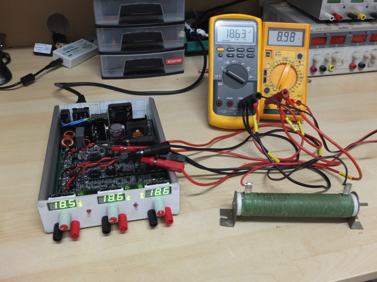
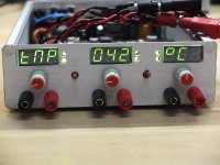
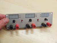
You can see below a panel picture when we use the temperature sensor measurement.

On this other picture, you can see the EPSUX3v3 operating
with slave mode of channel 2 and 3 (master CH1), where
all channel are connected in parallel to get 9A at 18.6V ! ( 166W).
My big 2R 100W resistors has started to smell bad very faster...
It is possible also to combine all outputs in series to get more voltage (60V 3A).
Now, i must drill the enclosure and panels.
After that, i will send design files to make beautiful Lexan panels.
I start also to write the "preview" manual, describing how to use it and to
summarize technical specifications.
To soon.
FRex
Hello all,
The CPLD Rev 1.0 is fully programmed and functional.
All needed functions is implemented and work fine.
A big step has been reached today, i tested the EPSUX3v2 as a whole :
The off-line primary smps (PFC+LLC converter) powering
all three regulators boards (EPSUX3REGv1) as expected.
And the result, all work fine.
You can see below a panel picture when we use the temperature sensor measurement.
On this other picture, you can see the EPSUX3v3 operating
with slave mode of channel 2 and 3 (master CH1), where
all channel are connected in parallel to get 9A at 18.6V ! ( 166W).
My big 2R 100W resistors has started to smell bad very faster...
It is possible also to combine all outputs in series to get more voltage (60V 3A).
Now, i must drill the enclosure and panels.
After that, i will send design files to make beautiful Lexan panels.
I start also to write the "preview" manual, describing how to use it and to
summarize technical specifications.
To soon.
FRex
Attachments
Hello,
Thank you Turbon !
The work is in progress again...
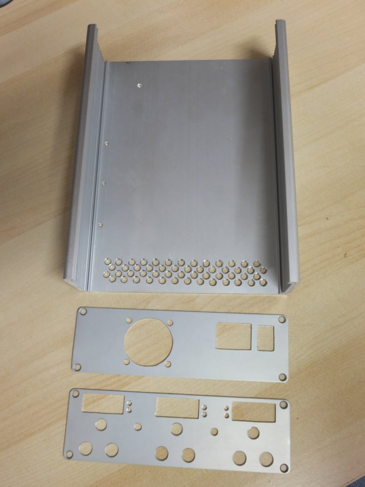
This week, i've made all panels and the base.
All has been manually drilled and filed down.
Take some time and patience!
This week-end i will try to build all of of that.
That begin to take shape...
I've also work a lot on writing the preview manual, i try to post it
these days.
For finish, a small picture of the newly made panels :
Frex.
Thank you Turbon !
The work is in progress again...
This week, i've made all panels and the base.
All has been manually drilled and filed down.
Take some time and patience!
This week-end i will try to build all of of that.
That begin to take shape...
I've also work a lot on writing the preview manual, i try to post it
these days.
For finish, a small picture of the newly made panels :
Frex.
Attachments
In the box !
Hello all,
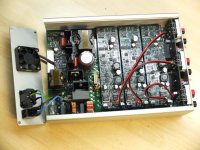
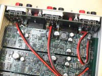
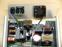
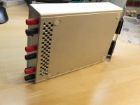
All circuits boards are now mounted in enclosure, and all fits very well.
All internal wiring has been made also.
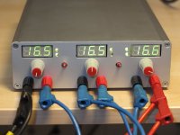
After these mechanical check, i did a thermal test at maximum power
(three outputs in series at 16.6V and 3.2A for 160W at output).
This test lasted for 4 hours at full power successfully, and the internal
temperature has reached 52°C (Tamb=22°C). At this temperature,
the fan is not at full speed.
I'm very happy with that result, the forced air flow seem to work well.
Of course, bottom front openings are very important...
Some pictures below of the mounting and test.
From now, i will continue on working for Lexan panels designs,
and also on some CPLD improvements. I think to switch wirings of CH1 and CH3
on front panel to avoid long output wires and keep them more away of all
magnetics parts that could be coupling with outputs wires.
I plan of course to do some extensive measurements on finished PSU.
Frex

Hello all,
All circuits boards are now mounted in enclosure, and all fits very well.
All internal wiring has been made also.
After these mechanical check, i did a thermal test at maximum power
(three outputs in series at 16.6V and 3.2A for 160W at output).
This test lasted for 4 hours at full power successfully, and the internal
temperature has reached 52°C (Tamb=22°C). At this temperature,
the fan is not at full speed.
I'm very happy with that result, the forced air flow seem to work well.
Of course, bottom front openings are very important...
Some pictures below of the mounting and test.
From now, i will continue on working for Lexan panels designs,
and also on some CPLD improvements. I think to switch wirings of CH1 and CH3
on front panel to avoid long output wires and keep them more away of all
magnetics parts that could be coupling with outputs wires.
I plan of course to do some extensive measurements on finished PSU.
Frex
Attachments
-
 EPSUX3V2_inbox_02.jpg122.7 KB · Views: 121
 -
 EPSUX3V2_inbox_03.jpg124.4 KB · Views: 122
 -
 EPSUX3V2_inbox_06.jpg245.5 KB · Views: 154
 -
 EPSUX3V2_inbox_07.jpg298.3 KB · Views: 177
 -
 EPSUX3V2_inbox_08.jpg211.5 KB · Views: 152
 -
 EPSUX3V2_inbox_09.jpg120.4 KB · Views: 137
 -
 EPSUX3V2_inbox_17.jpg126.1 KB · Views: 113
 -
 EPSUX3V2_inbox_18.jpg113.6 KB · Views: 118
Looks excellent. I'm wondering are you going to find out temperatures on input rectifier diodes and output LDO on one of the three modules? I believe that it will be well within safe area but it could be helpful information for other designers how are going to replicate your design.
- Home
- Design & Build
- Equipment & Tools
- Triple outputs 160W Lab PSU -- EPSUX3 version 2 !