Happy new year Frex and everyone on the forum!
DAC resolution
I would select 10 or 12 bit dac. Let's say you want 13,8 volt. You turn the knob and read 13,76 volt on your Fluke. Then one 'bip' on the knob will take you to 13,84 because 1 LSB = 0,08 volt. The best way would be when one 'bip' equals one significant digit.
By the way, you have 80mV resolution in range 10,24-20,48 volt. Below 10,24 volt, you can set gain bit in dac to 0 (ie dac value is multiplied by 2,048V) and have 255 steps (with MCP4802!) in range 0-10,24V and a resolution of 40mV.
ADC filter
Ok, you have the built circuit and have the oscilloscope, I trust you! It is just that I read in the datasheet http://ww1.microchip.com/downloads/en/DeviceDoc/21034D.pdf in section 4.1 that "Ideally, the impedance of the signal source should be near zero." They do that by connecting opamp output directly to adc input. Also look at figure 6-3 how they design an input filter.
This is a very exciting design and I will get back with more questions and comments!
Calibration of the measured voltage is needed. In a perfect world, the ADC will return 100 for 1 volt. This because
(2^12 / Vref) * (R39/(R39+R38||R33)) = (4096/4.096)*(1000/(1000+9000))=100
But Vref can be in range 4,055-4,137 according to the datasheet. And the resistors have 1% tolerance. So the worst case upwards is
(4096/4,055)*(1010/(1010+8910))=102,84
In other words, you can have a +/- 2,84% error of measured voltage. If you have for example an actual value of 20V, this may read 20,56V on the display. ok, this will very rarely happen, but it can happen!
You can fix this by adding a trim-pot between R39 and R33, but this is not optimal. Best is to have calibration. The error is linear so you only need to do one measurment.
But now that you, I hope, have accepted calibration, you can simplify the design. The improved accuracy of R38 and R33 in paralell is imaginary, it is still 1% tolerance for them both. So you can remove R38 from your design and make R33 9kOhm 5-10% and make R39 1kOhm 5-10%. Errors will be reduced by the calibration.
Hello PH01,
The bips are only for signify crank of the rotary encoder to say if you increase (high-tone) or decrease (low-tone) the setpoint.
Using the gain block inside the DAC is a very good idea, i don't know why i don't have seen that !
Thank you. I will see to try this soon, just need to find time.
Buy the way, It's a good reason for me to keep with a 8 bits DAC...")
About ADC filtering, generally yes, we want to drive ADC with lowest impedance as possible.
But, the datasheet say also that sampling rate can reach it's maximum value with input impedance source up to 1kOhms (fig 4.2).
So, now about calibration, your calculations are right but your conclusion is too fast.
In real world, the error will reach that value.
In my own prototype, and without any specific precaution the error are resume in table below :
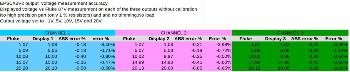
The error is only consistent when voltage become low (1V) but even 4% error at 1V output (40 mV!) is not a concern for most users.
So, there is many ways to improve actual accuracy.
I keep that in mind, with all others previous remarks.
Frex
The bips are only for signify crank of the rotary encoder to say if you increase (high-tone) or decrease (low-tone) the setpoint.
Using the gain block inside the DAC is a very good idea, i don't know why i don't have seen that !
Thank you. I will see to try this soon, just need to find time.
Buy the way, It's a good reason for me to keep with a 8 bits DAC...
About ADC filtering, generally yes, we want to drive ADC with lowest impedance as possible.
But, the datasheet say also that sampling rate can reach it's maximum value with input impedance source up to 1kOhms (fig 4.2).
So, now about calibration, your calculations are right but your conclusion is too fast.
In real world, the error will reach that value.
In my own prototype, and without any specific precaution the error are resume in table below :
The error is only consistent when voltage become low (1V) but even 4% error at 1V output (40 mV!) is not a concern for most users.
So, there is many ways to improve actual accuracy.
I keep that in mind, with all others previous remarks.
Frex
EPSUX3v2 Group-buy move on my blog page.
Hello all,
As some of you know, the wiki is unavailable since many weeks and will not be repaired
very soon as Jason has said here.
So, i had used a wiki page to organize the project group-buy and that become to be a problem.
So with the help of Jason, i've recover the list of DIYers of the wiki page.
So, today i wrote a blog page with all informations about the group-buy of the EPSUX3v2 project.
This blog page replace now the wiki.
The blog is HERE.
Until now, 12 pre-order are done on 25 required. We will wait end of February,
and then if we stay less than 25, i will make a new price estimation for a lower batch.
In parallel with that, i re-route each boards to make all needed fix, and also to allow easy voltage calibration (gain adjustment) as suggested by ph01.
I'll try to come back with news soon, and don't hesitate if questions if you hesitate to participate to the group-buy.
If interested, just send me a private message and i will add you in the list.
All the detail of the group buy can be found now HERE on my blog page.
Frex
Hello,
We are now the 06 March and there is 14 pre-order for the EPSUX3v2 kits
(PCBs+Lexan+regulators). So the target of 25 is not reached.
I think if at least 10 kit are order (from these 14) are confirmed,
i can look for the new price of the kit trying the stay with lower cost as possible.
But before i do this consuming time job, i ask pre-order confirmation to DIYers that will
really want to built this projects.
So, i ask to all interested DIYers that want to join the list to send me a PM with
your personal e-mail address and the number of kit requested.
(even if you are already in the pre-order list !)
Thank you !
Regards.
Frex
Hello Fabian,
For now, the requested minium order for the kit not reached, but nearly.
So i waited a little.
I continu to work on, in particular to finalize the Lexan panel.
I hope to order it next week to "Maverick Label. It is the only missing parts on my prototype...
I go in holidays this week-end, but i'll back soon with more more news.
Thank you !
Frex
EPSUX3v3 group-buy progress
Hello,
I work a lot these days to make a new precise price list for the group buy.
The prices I got are summarized below :
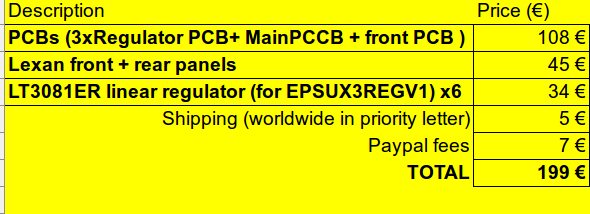
There is from now ten pre-ordering in the group-buy list,
so these prices are the better possible for a batch of ten.
I remind that the group buy is for building the EPSUX3V3 high performance power supply described in this thread.
As indicated in the previous table, it include all PCB(5) 4 layers with ENIG
gold finish, the professional front and rear Lexan panel (to make a very professional look to the PSU) and the six LT3081ER regulators needed.
You can look HERE how lexans panels looks like.
I apologize about the group-buy delay, but i had work a lot to make a serious design and also serious price evaluation.
I would understand if anyone want to leave the group buy because of price.
Please, inform me if it is your case.
Anyway, keep in mind that you will build yourself a very good PSU and you will not find it anywhere ! All design files will be provided to all group-buyers.
Also, of course if somebody is interested to join the grou-pbuy he can.
Just PM me.
Frex
Hello,
I work a lot these days to make a new precise price list for the group buy.
The prices I got are summarized below :
There is from now ten pre-ordering in the group-buy list,
so these prices are the better possible for a batch of ten.
I remind that the group buy is for building the EPSUX3V3 high performance power supply described in this thread.
As indicated in the previous table, it include all PCB(5) 4 layers with ENIG
gold finish, the professional front and rear Lexan panel (to make a very professional look to the PSU) and the six LT3081ER regulators needed.
You can look HERE how lexans panels looks like.
I apologize about the group-buy delay, but i had work a lot to make a serious design and also serious price evaluation.
I would understand if anyone want to leave the group buy because of price.
Please, inform me if it is your case.
Anyway, keep in mind that you will build yourself a very good PSU and you will not find it anywhere ! All design files will be provided to all group-buyers.
Also, of course if somebody is interested to join the grou-pbuy he can.
Just PM me.
Frex
Hello,
And thank you very much to all faithful DIYers wanting build the PSU.
For now, there is only 6 kits confirmed.
Some DIYers has not yet answered about their involvement in the group buy.
I've already spend much time to get price, and if in near delay (on week),
no ten kits are reached I will no continue the group buy.
In fact, even for 8 instead of 10 I would need to make another price estimation
and total price will increase again, and so buyers number will decrease again...
This is a no end circle...
If that happen, i will then only offer to orders bare PCB kit from me at lowest price possible.
But you will need to order all others parts by yourself.
LT3081 can be ordered directly from Linear or using Digikey and Farnell.
For the panels, a fully drilled and engraved front and rear panels will cost about 100€ from
FrontPanelExpress (like what i had done on the V1 of the PSU). The advantage compared
to a Lexan is that you have a fully drilled panel with beautiful cut (no need to machined the panels yourself).
So, i wait the end of next week to decide.
Best regards.
Frex
Hi Frex,
i'm interested in this really nice project (all boards and the LT3081er) but my problem is to solder and program the CPLD. I think the other parts are no problem for me.
When i remember right you wrote like this in the thread "when enough interests then you are think about to soldering ..." is this up to date?
Hello,
Jaac, ok i add you to the list. No problem for your back date.
Carsten, thank you for your interest.
You are right, i had thinking about for soldering CPLD some time ago.
Unfortunately, it was possible only for a much bigger PCBs order.
That would need a stencil for a re-flow soldering.
Doing this for a very low batch is not realistic.
But don't be discouraged, you can maybe do it ?
Soldering a TQFP144 can be done without issue if you have a good soldering iron,
good eyes and magnifying lens. And al little patience of course.
Many tutorial videos are available on youtube to show how you can do this
without soldering it pin after pin.
Regards.
Frex
- Home
- Design & Build
- Equipment & Tools
- Triple outputs 160W Lab PSU -- EPSUX3 version 2 !