Hello Prasimix,
Yes of course it's the red line to be connected !
So, you have also a little misundertood the AN104 schematic concept.
In this design, you will not need any load ! The circuit sink a constant current (corresponding to your resistor Rlo) using the DC bias potentiometer.
The input pulse signal at left (waveform input) allow the "jump" of the current between the previous bias current and the second value fixed by the input pulse amplitude (1V/A).This replace your second load Rhi.
Otherwise, your drawing can work with my simple short circuit tester.
Regards.
Frex
Hello Prasimix,
Yes of course it's the red line to be connected !
So, you have also a little misundertood the AN104 schematic concept.
In this design, you will not need any load ! The circuit sink a constant current (corresponding to your resistor Rlo) using the DC bias potentiometer.
The input pulse signal at left (waveform input) allow the "jump" of the current between the previous bias current and the second value fixed by the input pulse amplitude (1V/A).This replace your second load Rhi.
Otherwise, your drawing can work with my simple short circuit tester.
Regards.
Frex
True. Actually I worked simultaneously that night on both tester and forgot what is a main point of an104-15 circuit 🙂. Thanks for your remark (as it can also help cleaning mess what I made with that post).
Some news.
Hello all,
These previous weeks , i was working on CPLD software of the PSU.
I developed the code and testing new features with my prototype board.
And that take much time !
From now, the CPLD doesn't need any more external oscillator,
i use the internal one included in MAXII and MAXV devices.
That allow a small economy...
A newer functionality, it to used the internal UFM (universal flash memory)
block of the CPLD. This memory is used to store all settings values at switch off.
Thus, at the next start-up all previous V/I settings are recovered.
To work properly, i had added a small circuit allowing a fast shut-down detection.
This give time to write the UFM , before the CPLD voltage drop.
I also replaced the MCP9700 thermal sensor and it's comparator by a TC72 MSOP
digital thermal sensor with SPI link.
This IC allow to measure directly in °C the circuit board temperature, and read on one of the three leds display.
Internal CPLD registers contain the upper and lower thresholds that stops the PSU outputs.
The work is progressing, to be continued...
Of course all comments and suggestions is welcomed..🙂
Frex
Don't know did you have a time yet to test CC mode of operation. How it differ from CV mode (i.e. noise figure, precision/resolution etc.) and how PSU behave when it change mode from CV to CC and vice versa during normal operation and in special cases such as power up and down and output enable on and off.
Hello prasimix,
I've already done CC/CV mode of the EPSUX3REGv1 circuit, there is no difference between each.
The I/V control loop is fully done by the LT3081 regulators. So, the current to voltage mode is extremely fast.
No unexpected behaviours occurs in any listed circumstance you mention.
The disadvantage of that, is that i need to make my own error amp to detect the CC or CV mode
(no signal come from the regulator). I work actually to do that with the FPGA comparing settle
and measured voltage there-between.
Regards.
Frex
(NB: I will do some measurements and screen-shoot on CC/CV mode as soon i could).
Thanks Frex once again. I need some more inputs about measurements that are presented in #83. Did you deploy any additional capacitor on output or you simply tested mentioned devices as such? In your case you have CRC filter (47u+0R1+10u) on output. Nothing over that is used while testing?
Other thing just to be sure that I understood performance of other PSU: in case of Selectronic SL1731SB there is ~800mV overshoot for 12V for 1+1A step (that is ~6.6%). Is that correct?
Other thing just to be sure that I understood performance of other PSU: in case of Selectronic SL1731SB there is ~800mV overshoot for 12V for 1+1A step (that is ~6.6%). Is that correct?
Hello Prasimix,
Of course, i test the PSU without any external output capacitor.There is only the internal PSU output caps.
Yes, for the EPSUX3REGv1 test, there is only the 47uF cap on LT1081 followed by the two 0.1R shunt and and 10uF MLCC.
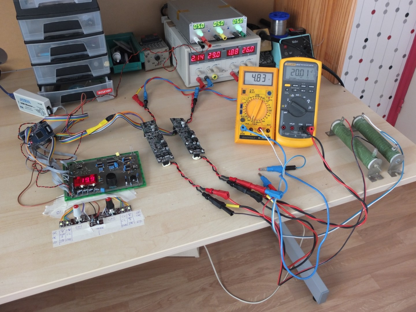
One of the picture on post #83 show the test fixture, you can see that the output (re/black wires) directly connected to test box.
Yes again, the SL1731 PSU give 800mV transient voltage for 12V 1A step !
Frex
Of course, i test the PSU without any external output capacitor.There is only the internal PSU output caps.
Yes, for the EPSUX3REGv1 test, there is only the 47uF cap on LT1081 followed by the two 0.1R shunt and and 10uF MLCC.
One of the picture on post #83 show the test fixture, you can see that the output (re/black wires) directly connected to test box.
Yes again, the SL1731 PSU give 800mV transient voltage for 12V 1A step !
Frex
Yes again, the SL1731 PSU give 800mV transient voltage for 12V 1A step !
😱 that's really not so good but it's question how it will looks like with adding capacitor on the load end (e.g. 22-100uF).
Summer project News...
Hello all,
Some news of the projets.
1 - CPLD program
I made again some works on CLPD to test all final functionality, validating
the final design.
The recovery of settings values after power off works fine. It use a voltage supervisor (MCP130-475) to detect voltage drop, and the UFM internal memory
block of the CPLD to record them quickly after this event.
Because the CV/CC regulation control mode is made internally of the LT1081,
and we have no access to the output error amp, it's the CPLD that detect
when CC or CV mode operate.
To do that, we digitally compare the voltage setting value with the real measured
output voltage value.
If this two value diverge of ~3% of setting value, it is considered that the CC mode is active. The performed tests with that gave good CC/CV mode indication.
2 - Combo regulator tests
I've already made several test on EPSUX3REG combo-regulator board,
but no parallel and serie mode operation has been made because until now only one of these circuit board has been wired.
So, actually i work on wiring the two others PCB, near to be finished.
Normally, each combo-regulator board must work in each serie/parallel mode
without issue.Of course, i want test it before !
So with the two PCB in series mode we could get up to 40V 3A and
20V 6A in parallel mode. I work on providing easy use of these modes.
Using the third available PCB, we could also get up to 10V 10A !
Many tests in perspective...
You can show my bench top with the wiring progress of the two others PCB below.
3 - Enclosure design
I also think about the enclosure design, to allow cheaper solution than engraved front and rear panel like the first version.
To get a professional look for a small batch of panels, i think that Lexan overlays would be very interesting solution.
It have many advantages :
I've found some interesting links to get this, you can feedback your opinion about them if you have been experienced with.
Custom Front Panels
They allow to buy directly drilled panel with the Lexan overlay for a reasonable cost,
they can directly use standard Hammond 1455 series panels !
Control Panel Graphic Overlay Printing And Prototypes
They have low cost Lexan for small batch (>=10), but drilled panel is not included
and we need to fix the overlay ourself.
I have done some search about that, but if you have interesting links i will appreciate.
As you could see, even if the work is fast, the project goes. 🙂
Many others news soon. Commend and suggestions welcome !
Regards.
Frex
Hello all,
Some news of the projets.
1 - CPLD program
I made again some works on CLPD to test all final functionality, validating
the final design.
The recovery of settings values after power off works fine. It use a voltage supervisor (MCP130-475) to detect voltage drop, and the UFM internal memory
block of the CPLD to record them quickly after this event.
Because the CV/CC regulation control mode is made internally of the LT1081,
and we have no access to the output error amp, it's the CPLD that detect
when CC or CV mode operate.
To do that, we digitally compare the voltage setting value with the real measured
output voltage value.
If this two value diverge of ~3% of setting value, it is considered that the CC mode is active. The performed tests with that gave good CC/CV mode indication.
2 - Combo regulator tests
I've already made several test on EPSUX3REG combo-regulator board,
but no parallel and serie mode operation has been made because until now only one of these circuit board has been wired.
So, actually i work on wiring the two others PCB, near to be finished.
Normally, each combo-regulator board must work in each serie/parallel mode
without issue.Of course, i want test it before !
So with the two PCB in series mode we could get up to 40V 3A and
20V 6A in parallel mode. I work on providing easy use of these modes.
Using the third available PCB, we could also get up to 10V 10A !
Many tests in perspective...
You can show my bench top with the wiring progress of the two others PCB below.
3 - Enclosure design
I also think about the enclosure design, to allow cheaper solution than engraved front and rear panel like the first version.
To get a professional look for a small batch of panels, i think that Lexan overlays would be very interesting solution.
It have many advantages :
- Low cost for small batch
- Very durable
- Beautiful aspect
- Avoid the use of cut windows for 7 segments leds display (translucent overlay area)
I've found some interesting links to get this, you can feedback your opinion about them if you have been experienced with.
Custom Front Panels
They allow to buy directly drilled panel with the Lexan overlay for a reasonable cost,
they can directly use standard Hammond 1455 series panels !
Control Panel Graphic Overlay Printing And Prototypes
They have low cost Lexan for small batch (>=10), but drilled panel is not included
and we need to fix the overlay ourself.
I have done some search about that, but if you have interesting links i will appreciate.
As you could see, even if the work is fast, the project goes. 🙂
Many others news soon. Commend and suggestions welcome !
Regards.
Frex
Hi Frex,
Thank you for the update.
It is good to see the progress, time is not so significant to achieve these results.
I have no experience with the manufacturers you mentioned, but I think, both solutions will not be cost effective, based on their location for a DIY project. I think you have tried in the past http://www.schaeffer-ag.de/en/.
BR
Last edited:
Project news, regulator serie/parallel mode - CC/CV mode -Video to come..
Hello all,
After a very hot holidays (well-deserved) in July, i continue the project progress.
Spirtos, thank you for your comment.
Effectively the Schaeffer panels are beautiful, but the price for a batch doesn't drop very much and become too high.
I really think that Lexan on drilled panel will look very good for much less.
Another thing, is that with a Lexan, the surface finish of the drilled panels do not need to be perfect because Lexan will hide all.
The green windows will not need to be made and glued also, they will be inside Lexan too. All of these are probably more DIY friendly.
Maverick has already send me some sample (for free) overlays and they looks very good. I will probably order a prototype pair (front and rear) as soon the panel design will be ready.
These days, i have done some tests with two combo regulator board EPSUX3REGV1 to test tracking mode operation.
I have test it in serial mode without issue, and allowing to get up to 40V with 3A.
I have also made more critical tests, the parallel mode operation.
And it work well.
With two EPUX3REGv1 circuits boards, i can get up to 20V 6A (120W) .
Many functions of CPLD and SPI link has been tested successfully.
Because sometimes it's more meaningful, I've made a 14 minutes movie to show some test review and how parallel mode work and CC/CV operation of the boards.
I upload the movie right now and that take some time...
I will post the link as soon it's done.
My main concern before to finalize the main board was the parallel mode behavior of the regulator boards. Now, the next step is to finish it...
Next week, i will post updated schematics of regulator and main board.
Frex
Before the full video, the bench setup of parallel mode test below
Nice video and progress Frex.
From what you say, lexan seems better solution. You are correct about the drilling, windows etc. I have no info regarding prices, you know better about this.
Do you plan to include front and rear panel to group buy?
BR
From what you say, lexan seems better solution. You are correct about the drilling, windows etc. I have no info regarding prices, you know better about this.
Do you plan to include front and rear panel to group buy?
BR
Hello,
It's a little early for a group buy. So, i will probably try to offer many parts to greatly simplify the build of the project to any experienced DIYers.
They are :
- The 2 circuits boards.
- The Lexans rear and front panel.
- The LLC Transformers and PFC inductors.
- The possibility to get main board with CPLD soldered/programmed as option.
With Lexans, panel drilling are much less critical. I think most DIYers could do some holes easily.
For the transformers, because it's more heavy than PCB or Lexan to send them all around the world at reasonable cost, that depend on how many i will need to order to a local manufacturer (France).
Maybe only sending the Litz wire not easy to sale (lightweight) instead of the full transformer could be also a good option.
Frex
Frex I have been following and really enjoy seeing the progress.
However, don't you think that 20v is a bit low ?
Eg for bench testing a typical power amplifier we need min 25-40 v dual rail.
However, don't you think that 20v is a bit low ?
Eg for bench testing a typical power amplifier we need min 25-40 v dual rail.
Hello Kasey,
I don't have think this PSU mainly to test power amplifier.
But it can, supply up to 60V 3A if your amplifier need single asymmetric voltage.
Each outputs can deliver 20V and can be connected in series to get this voltage.
If you need symmetric voltage more than 20v, you can maybe look the Prasimix PSU design that seem to be more suited to your needs.
Frex
EPSUX3V2 main board work.
Hello all,
These days, a big step has been reached. The main circuit board of the EPSUX3v2 has been fully draw.
I've send Gerbers files yesterday to manufacturer and i will get it in about ten days. (from WE-direkt).
This circuit board include the main board (loff-line SMPS / Logic ) and the front panel display board.
Some little improvements and modifications has been done on this design, and you can see the final schematics below (pdf file):
EPSUX3V2_sch.pdf
Below, you could see how the PCB looks like.
A pdf file of the board layout can be see also:
EPSUX3V2_pcb.pdf
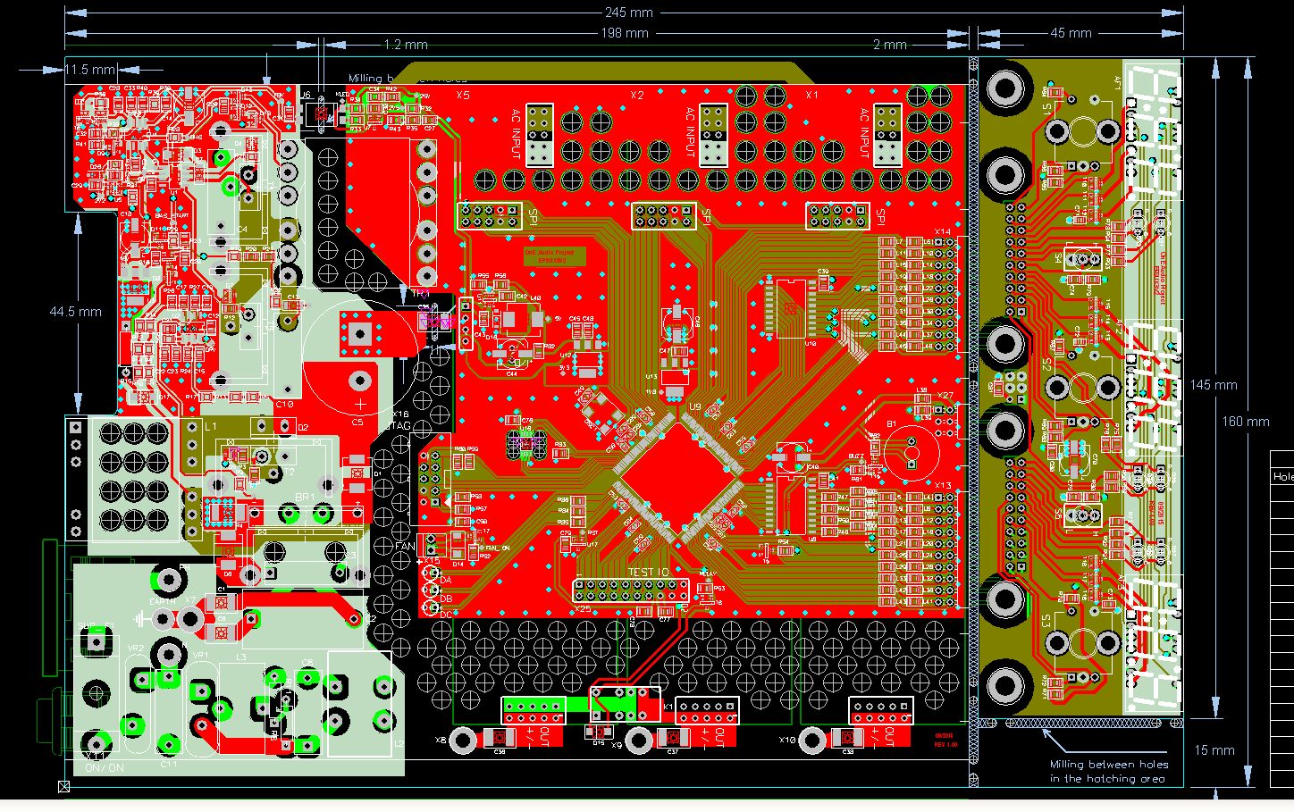
In parallel with the drawing, i have ordered some missing parts that i will receive soon. The soldering could start as soon i receive the PCB.
I continue to working on mechanical drawing and Lexan panel design.
To be continued...
🙂
Frex
Hello all,
These days, a big step has been reached. The main circuit board of the EPSUX3v2 has been fully draw.
I've send Gerbers files yesterday to manufacturer and i will get it in about ten days. (from WE-direkt).
This circuit board include the main board (loff-line SMPS / Logic ) and the front panel display board.
Some little improvements and modifications has been done on this design, and you can see the final schematics below (pdf file):
EPSUX3V2_sch.pdf
Below, you could see how the PCB looks like.
A pdf file of the board layout can be see also:
EPSUX3V2_pcb.pdf
In parallel with the drawing, i have ordered some missing parts that i will receive soon. The soldering could start as soon i receive the PCB.
I continue to working on mechanical drawing and Lexan panel design.
To be continued...
🙂
Frex
Hello Carpin,
I don't have ordered the stencil, all the circuit board will be hand soldered.
No parts require oven soldering like the previous PCBs (thermal pad).
And only the CPLD (TQFP144) will require good skill and patience to be soldered properly. Just take time...
Frex
I don't have ordered the stencil, all the circuit board will be hand soldered.
No parts require oven soldering like the previous PCBs (thermal pad).
And only the CPLD (TQFP144) will require good skill and patience to be soldered properly. Just take time...
Frex
- Home
- Design & Build
- Equipment & Tools
- Triple outputs 160W Lab PSU -- EPSUX3 version 2 !