hi WASTd, here is the schemaic I downloaded. unfortunately I did not save the URL where I found it.
Thank you so much, do I need to supply 3.3v? or would 5v be ok? it says main power supply shall be 5v [pin18]. but also states that the IC power supply voltage is 4.2V.
do I supply the chip through pin-18 with 5v? Any idea where pin 18 is located on the tpa3116?
Hi, begginer question, I’m looking for low power (5w) for small speakers which can work from 5v USB.
Modern D class chips looks like the best solution. The problem is two boards I tested have little but very annoing buzzing and strange chirpy distortions on high freq. (Chip TPA3116 and similar).
I cheked with osciloscope and saw high frequency noise (100kHZ) on output.
Is it possible to find D class amp with clear sound and not expencive?
Standard USB ports can deliver only 2.5W!
Or you will use a phone charger, which can deliver 2-3A(10-15W)?
Also if you use 4ohm speakers - from 5V power supply you can expect no more than 2W per speaker in BTL configuration.
There are several PAMxxxx class D chips for 5V operation in BTL mode.
Or you will use a phone charger, which can deliver 2-3A(10-15W)?
Also if you use 4ohm speakers - from 5V power supply you can expect no more than 2W per speaker in BTL configuration.
There are several PAMxxxx class D chips for 5V operation in BTL mode.
Thanks. Today I tryed again litte board marked “XH-A232” with shelf speakers and powered from old chellphone charger, marked “5.7V 800mA”.
And result was ok, loud enouf for small room, buzzing noise only audible when sitting very close to speakers.
One problem - several times amp started “self excitatation”, sounds like digital 50Hz hum, and after power off/on it was fine. Same with different power supply.
Maybe board needs input RC filters.
Hi, begginer question, I’m looking for low power (5w) for small speakers which can work from 5v USB.
Modern D class chips looks like the best solution. The problem is two boards I tested have little but very annoing buzzing and strange chirpy distortions on high freq. (Chip TPA3116 and similar).
I cheked with osciloscope and saw high frequency noise (100kHZ) on output.
Is it possible to find D class amp with clear sound and not expencive?
These ae a very good implementation of the PAM8406 chip, which can run in D Class (default) or A/B Class.
I have used them to build active speakers and to convert vintage radios into BT speakers (there is a 'matching' BT board which works very well).
On a decent phone charger wall wart they are totally silent, and will run for hours on a 10000mAH battery bank.
You can get them for under $5/5€ on AliExpress if he Amazon pice is too high!
https://www.amazon.com/PAM8406-Amplifier-Digital-Channel-Amplify/dp/B08RDN58SZ/ref=sr_1_3?keywords=pam8406&qid=1636442960&sr=8-3
Edit: Here's he matching BT board:
https://www.amazon.com/Bluetooth-DROK-Receiver-Electronics-Headphone/dp/B07P94Z9XR/ref=bmx_dp_8/133-1223925-4494607?pd_rd_w=dmLcU&pf_rd_p=b7fa5431-ff87-43ac-9073-fcdf928ec25c&pf_rd_r=XA15FYTBQB30Q5G4RQXP&pd_rd_r=cf9d772c-6c1a-4750-8933-8b496e747856&pd_rd_wg=Otr81&pd_rd_i=B07P94Z9XR&psc=1
Last edited:
Modern D class chips looks like the best solution. The problem is two boards I tested have little but very annoing buzzing and strange chirpy distortions on high freq. (Chip TPA3116 and similar).
I cheked with osciloscope and saw high frequency noise (100kHZ) on output.
Is that distortion present between the + and the - ? On my amp, I have frequency parasite relative to the ground (I guess it comes from the PSU), but almost, but almost none between the connector (the amp is bridged), the - and the + resting position is at vcc/2.
At those high frequency, the length of the speaker cable can be enough to dampen it. If you measure it near the amplifier, it'll be higher than what the speaker will actually see. Due to its inductance and its capacitance, a cable is intrinsically a low pass filter.
Hi, begginer question, I’m looking for low power (5w) for small speakers which can work from 5v USB.
Modern D class chips looks like the best solution. The problem is two boards I tested have little but very annoing buzzing and strange chirpy distortions on high freq. (Chip TPA3116 and similar).
I cheked with osciloscope and saw high frequency noise (100kHZ) on output.
Is it possible to find D class amp with clear sound and not expencive?
Where is the input from? Where is the 5V supply from?
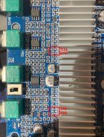
Yes, to me it seems the gain resistors are the ones I highlighted in the attached photo.
Hello Trileru, I have the exact same board, and was trying to adjust the gain. but I found out that the ones you highlighted on the photo have a value of 33k and 67k, and on the bottom chip (master?) they are 44k and 39k. Am I looking at the right resistors? because these values seem kind of odd to me.
Attachments
I think the heatinsk is screwed down? If so then it wouldn't be complicated to take it out and measure continuity between those resistors and pins 7 and 8 of the audio chip. If they are connected then you can adjust them per datasheet.
edit: if the photo is of your actual board then it has the correct resistors for the 32dB gain setting. Based on the values written on the resistors in the photo.
edit: if the photo is of your actual board then it has the correct resistors for the 32dB gain setting. Based on the values written on the resistors in the photo.
Last edited:
I think the heatinsk is screwed down? If so then it wouldn't be complicated to take it out and measure continuity between those resistors and pins 7 and 8 of the audio chip. If they are connected then you can adjust them per datasheet.
edit: if the photo is of your actual board then it has the correct resistors for the 32dB gain setting. Based on the values written on the resistors in the photo.
It is indeed of my actual board, would I need to replace the thermal paste if I take off the heatsink?
Depending on how loud you listen to. I don't think I attached the heatsinks back on my boards. But I don't listen to loud music.
I think in this chip's case any kind of thermal paste would be fine, as long as you're not totally stressing it out.
If the original is not hardened you can try and recycle it.
I think in this chip's case any kind of thermal paste would be fine, as long as you're not totally stressing it out.
If the original is not hardened you can try and recycle it.
Depending on how loud you listen to. I don't think I attached the heatsinks back on my boards. But I don't listen to loud music.
I think in this chip's case any kind of thermal paste would be fine, as long as you're not totally stressing it out.
I would say I listen to loud stuff, should I make sure before I desolder the resistors I have marked?
If that's your actual photo then you don't need to take the heatsink off. You just replace the resistors.
You'd need to take the heatsink out to verify they are indeed connected to the gain pins of the chip. But most likely they are, since they have the correct values for 32dB setting. You should go to the 20dB setting.
It's not reliable to measure resistor value in-circuit, with a dmm. There are devices that can do this, but I wouldn't trust a dmm value for an in-circuit resistor.
If that's your actual photo then you don't need to take the heatsink off. You just replace the resistors.
You'd need to take the heatsink out to verify they are indeed connected to the gain pins of the chip. But most likely they are, since they have the correct values for 32dB setting. You should go to the 20dB setting.
It's not reliable to measure resistor value in-circuit, with a dmm. There are devices that can do this, but I wouldn't trust a dmm value for an in-circuit resistor.
Unfortunately thats the only measuring tool on my hand. So you're saying I should make sure that these resistors are indeed tied to the pins? It is my actual photo. I just dont want the trouble of going through an extra step
I think you can safely replace them directly.
Just make sure you correctly install them. If the upper chip is slave and the lower is master, then you replace the lower 39K resistor (393 code on it) with a 5.6K resistor. The lower 100K resistor you completely remove.
For the slave (upper chip) you replace the 100K resistor with 51K and the 39K resistor with 51K as well.
The only thing I don't understand is the smd code on the 100K resistor. Should have been 104. It's simpler to just remove it and measure it with DMM.
I think you can safely replace them directly.
Just make sure you correctly install them. If the upper chip is slave and the lower is master, then you replace the lower 39K resistor (393 code on it) with a 5.6K resistor. The lower 100K resistor you completely remove.
For the slave (upper chip) you replace the 100K resistor with 51K and the 39K resistor with 51K as well.
The only thing I don't understand is the smd code on the 100K resistor. Should have been 104. It's simpler to just remove it and measure it with DMM.
My apologies if this sounds stupid but none of the resistors I have marked measured 100k.
You must first remove them from the pcb, them measure them with DMM.
Interesting how it is 101, will remove from the PCB and measure, thank you so much!
- Home
- Amplifiers
- Class D
- TPA3116D2 Amp