
Large (100 μF or greater) bulk power supply decoupling capacitors should be placed near the TPA3116D2 on the PVCC supplies. Local, high-frequency bypass capacitors should be placed as close to the PVCC pins as possible. These caps can be connected to the IC GND pad directly for an excellent ground connection. Consider adding a small, good quality low ESR ceramic capacitor between 220 pF and 1 nF and a larger mid-frequency cap of value between 100 nF and 1 μF also of good quality to the PVCC connections at each end of the chip.
3caps
>100uf, 1uF, 1nF
Choose a ecap can size that will all you to go up in value.
Best to use 1206/0805 pkg for most passives except for ecaps, input coupling cap possibly a dual footprint. Looks like you have a 7.5-10-15mm lead spacing?
If you do not mind, can you post the Eagle file(s), I can look at it better that way. I have a gerber viewer as well, so I can check the CAM o/p for anything that looks off.
Choose a ecap can diam size that will allow you to go up in value by changing can length.
Best to use 1206/0805 pkg for most passives except for ecaps, input coupling cap possibly a dual footprint. Looks like you have a 7.5-10-15mm lead spacing?
If you do not mind, can you post the Eagle file(s), I can look at it better that way. I have a gerber/CNC viewer as well, so I can check the CAM o/p for anything that looks off.
Take care
Rick
Best to use 1206/0805 pkg for most passives except for ecaps, input coupling cap possibly a dual footprint. Looks like you have a 7.5-10-15mm lead spacing?
If you do not mind, can you post the Eagle file(s), I can look at it better that way. I have a gerber/CNC viewer as well, so I can check the CAM o/p for anything that looks off.
Great, i'd like to hear about your progress, testing, performance, configuration etc. Wonder how well it compares to others. Send me a PM and we can continue discussion or start our own thread.Well, in that school project I got the NDA, signed the NDA, got the full datasheets and serial protocols. We haven't even bought one module from the company!
We got a development board from: DAB DAB+ FM Digital Radio Development Board Pro with SlideShow
This board has the T1-L4A-8650C, it has even more functionality. (but serial protocol is the same)
The same guy from that company also sold us some 8290 modules to develop with. (we made our own pcb)
Take care
Rick
Last edited:
I refined my first board for mass use but never went past design.
China stuff too cheap to compete.
Like some people have mentioned here...buy one of theirs and modify it.
When I thought of designing my own board it was more of interest of trying the TPA3118 than anything else, as YJ its only with the 3116, and I wanted to try the 3118 becouse it seems to be better for 8ohms speaker. Of course we can compete with that, but at that moment never thought in any economical benefit.
Beside saying this, Im a total newbie in electronics, Im able to take a simple schematic like the one in the TI datasheet and make a pcb but I wouldnt be able to make my own amplifier design circuit.
The 5cmx10cm board Im working I Will try to make it as more universal as posible, so it can be used with wima caps for the output filter or smd caps, as in the input caps can be used jantzen audio caps or similar, wima caps or smd caps, each one chooses what component to use, the same for the inductor, shielded or coils...
Looking forward seeing the results!The 5cmx10cm board Im working I Will try to make it as more universal as posible, so it can be used with wima caps for the output filter or smd caps, as in the input caps can be used jantzen audio caps or similar, wima caps or smd caps, each one chooses what component to use, the same for the inductor, shielded or coils...
If you need help designing the pcb, don't hesitate to contact me
")
Last edited:
Get your BOM together and we can review it. As you are finding out, a few decisions need to be made as far as component choices. reading data sheets, making libraries. Making it as universal as you can, is a a good choice, to a limit. As you will/are finding out, film capacitors, TH R's take up a large amount of pcb area compared to SM versions.
Look at your task as one module/piece of a complete system(stereo).
I used the Murata shielded coils, they work good for me.
Good Luck
Rick
Look at your task as one module/piece of a complete system(stereo).
I used the Murata shielded coils, they work good for me.
Good Luck
Rick
Alright.
I have tried this thing with both modulation modes and with almost all possible power supply/gain/voltage/input/output filter combinations and so far the best thing for me is to have two tpa3116 2x50W boards in pbtl. Still, when compared to a tk2050 2x 100W pbtl the sound from the tpa3116 is very weak from 20 to 700Hz.
Anyone else compared the tpa3116 with a tk2050 in pbtl ?
If so please, post your opinions and also the tk2050 board you have used for comparison.
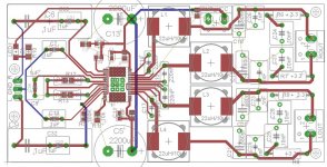
Here its a little pic of what Im doing...
look at the input caps on the left side, top and bottom of how there is the print of a large cap like a jantzen cross cap, then a wima 7x5mm and a 0603smd like suggested in the datasheet of the TPA3116EVM board.... The same with the other 1uF caps, the gain resistors... will do the same with the 220nF at the output side of the IC...
About suggested BOM, thats fine... I dont mind meanwhile the package its in the eagle library.
Attachments
Last edited:
Just a quick +1 on LiFePO4 batteries- much less hassle than 'normal' LiPOs. I use them in a heavyweight combat robot, and if they'll tolerate that, you'll be OK powering an amp! Very fast charging is possible and energy storage for the size and weight of the packs is excellent. On the basis of this and similar threads I've ordered a couple of the Sure 3110 boards. Very encouraging to read about the reported quality of this family of amps- they're certainly cheap enough to try out just for fun.
Alright.
I have tried this thing with both modulation modes and with almost all possible power supply/gain/voltage/input/output filter combinations and so far the best thing for me is to have two tpa3116 2x50W boards in pbtl. Still, when compared to a tk2050 2x 100W pbtl the sound from the tpa3116 is very weak from 20 to 700Hz.
Anyone else compared the tpa3116 with a tk2050 in pbtl ?
If so please, post your opinions and also the tk2050 board you have used for comparison.
That's exactly what I was going to do, use two boards for 2 channels. My current speakers are too insensitive. I was going to buy that from China but then it suddenly disappeared.
Can you elaborate on
"the sound from the tpa3116 is very weak from 20 to 700Hz" as comapre to the tk2050.
Regards,
Here its a little pic of what Im doing...
look at the input caps on the left side, top and bottom of how there is the print of a large cap like a jantzen cross cap, then a wima 7x5mm and a 0603smd like suggested in the datasheet of the TPA3116EVM board.... The same with the other 1uF caps, the gain resistors... will do the same with the 220nF at the output side of the IC...
About suggested BOM, thats fine... I dont mind meanwhile the package its in the eagle library.
Thanks for the dedication to designing this board and providing enough thru-holes to include our preferred components. In looking at your layout, it looks like there is a missing connection between R9 and C28 on the left channel output.
Thanks for the dedication to designing this board and providing enough thru-holes to include our preferred components. In looking at your layout, it looks like there is a missing connection between R9 and C28 on the left channel output.
There are several mistakes on the board as is but I consider it a draft.
Thanks for the dedication to designing this board and providing enough thru-holes to include our preferred components. In looking at your layout, it looks like there is a missing connection between R9 and C28 on the left channel output.
What I showed its how its going... Not finished yet... I still have to add the option of smd for the output... And recheck everything... Then the last step its to make all the GND plane...
There are several mistakes on the board as is but I consider it a draft.
Saturnus, please comment freely whatever you see... All Help its all welcome without offense, as I said before Im a total newbie in electronics, so its easy that I make mistakes...
Saturnus, please comment freely whatever you see... All Help its all welcome without offense, as I said before Im a total newbie in electronics, so its easy that I make mistakes...
Well. There's several comments
1) The chip has differential input so all 4 input caps must be identical. Also the ones connected to ground.
2) There should not be connections under chip other than GND connections to the GND pad.
3) Bootstrap capacitors should not be polypropylene or similar. It must be ceramic or tantalum and must be as close to the chip as possible. No more than 5mm maximum.
4) Filter inductor should either be grouped 1x4 or 2x2. If space does not permit that then should be placed so they are a little apart from eachother and grouped around the chip.
5) Filter output GND should be connected directly to the GND pin associated with that particular output and then to the GND pad.
6) All analog GND should be connected directly to the analog GND pin and then to the GND pad
Then there are some routing mistakes but I reckon they'll be cleaned up eventually as the other points are corrected so I won't comment on those yet.
Last edited:
I see you are combining through-hole and SMD, that is exactly what I was thinking about my design.Here its a little pic of what Im doing...
look at the input caps on the left side, top and bottom of how there is the print of a large cap like a jantzen cross cap, then a wima 7x5mm and a 0603smd like suggested in the datasheet of the TPA3116EVM board.... The same with the other 1uF caps, the gain resistors... will do the same with the 220nF at the output side of the IC...
About suggested BOM, thats fine... I dont mind meanwhile the package its in the eagle library.
@Saturnus: Thank you for your advice. I can see you have a lot of knowledge about this.
danzz and LVL,
Please be encourage for your fine efforts. Thank God for Saturnus' sage advice. I do not have skills or the patience to design compact circuit boards like these. I am sure that there are many others like me watching this thread cheering you on silently that a great PCB design will result, and that we can all share the fruits of your labors.
Please be encourage for your fine efforts. Thank God for Saturnus' sage advice. I do not have skills or the patience to design compact circuit boards like these. I am sure that there are many others like me watching this thread cheering you on silently that a great PCB design will result, and that we can all share the fruits of your labors.
danzz and LVL,
am sure that there are many others like me watching this thread cheering you on silently that a great PCB design will result, and that we can all share the fruits of your labors.
Same here
- Home
- Amplifiers
- Class D
- TPA3116D2 Amp