The standard approach to this is to leave the resistors and change the caps (of course, you can do it by changing the resistors as you indicate).
Pick two caps from available values to balance two factors: (1) The Fc or cut off frequency; and (2) The Q of the filter.
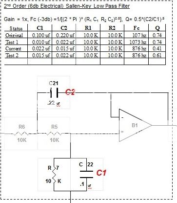
With the original 47K resistors, and selecting standard value caps: Change C1 to 33nf and C2 to 47nf (top cap in photo). This gives you a Fc of 86hz and a Q of 0.6. This places the 2nd order LP filter squarely between a 2nd order maximally flat Butterworth (Q=0.7) and a 2nd order Linkwitz-Riley filter (Q=0.5).
On my amp I went the other way crossing a 2.1 boombox with an Fc at ~876hz. Pre-modification, my Fc was 107hz. I've modified the amp twice, 1st was at 1073hz needed to go lower. For all three variations (original, 876hz and 1073hz), measurements validated the calculations.
But I'm confused, the original SMT resistors were 47K according to the silkscreen. The new axial resistors are also 47K? Was the board populated with different resistor values than the silkscreen's 47K designations (like the one polyester black cap: silkscreen 33nf, populated 68nf)?
No, the smd resistors I removed where marked 472 = 4.7kΩ
I see if I could find any caps to try out the filter.
Thanks for your patience.
Hmm,I´m confused.Change C1 to 33nf and C2 to 47nf (top cap in photo). T
You mean those electrolyt caps marked C1-C2 on your photo?
Or C21-C22 as marked C1-C2 on the schematic?
No, the smd resistors I removed where marked 472 = 4.7kΩ
I see if I could find any caps to try out the filter.
Thanks for your patience.
Oh, that explains a lot. With those two resistors originally miss-populated with 4K7 and the two caps at 68nf, then the Fc of the filter would have been 500hz. As you say, useless for your application.
And we've all been confused (comes from me trying to squeeze in these posts during 5 minute breaks from work). The red C1, C2 are the designations in the standard filter equation (corresponding to C22 & C22 on the schematic). Here's a simpler approach:

And I had another error is my earlier post ... With the two axial resistors now at 47K and C1 at 33nf, C2 at 47nf, your Fc will be 98hz, with a Q of .7 (2nd order butterworth).
If you make both caps 47nf, then your Fc will be 72hz with a Q of .5 (2nd order Linkwitz-Riley).
I'm in the USA and order from China via eBay because its very cheap and we don't have any more local stores with parts such as these. So if you ordering caps, Id get all those values to experiment.
And I love to know how it turns out ...
Last edited:
I am a noob looking for my first amp project. I have only read about 425ish pages of this thread, that includes the first 385ish, and the last 50 or so. At around 385 the consensus seemed that the blue daanz yj board was a solid board and a modder's dream. Fast forward to the end and most seem to have done a 180. What happened?
My plan is to get at least two, two channel boards, leaving one stock and playing with the other. I also plan on doing a DIY kit for a preamp when I finish tweaking the boards. This is as much a learning exercise for me as it is a quest for good sound.
I would rather pay a little more for a solid eBay seller with good shipping turnaround than price shop on aliexpress and hope for the best while waiting weeks or even longer for what I order to arrive. Would someone make a recommend for a supplier/board?
Huge props to the many contributors on this thread, the knowledge and experience you guys have shared is amazing,
Mrmky,
At the time, the Danzz blue was the first available with through holes and semi decent parts and up to that point, ok layout. It can still be quite good with good caps installed and bootstrap snubber, and proper inductor and output filter values and quality. What happened was as time went on, YJ started using random "whatever was closest" to the 680nF output filter caps and the quality of the inductors and main power caps were sub standard.
Around the same time, other boards like the Audiobah green, Ybdz Wiener, and custom made boards by Dug and Gmarsh came along as well as the SMSL 36A pro boxed amp. These amps started using tighter layout and high quality caps which are key to good sound quality.
Fast forward some more and amps like SMSL are now starting to suffer cap deletions, and out right chip substitutions to a TDA7492 without notice.
So back to question of a good first amp?
I still think if you like to use through hole parts to upgrade your amp, the Danzz blue is a viable and decent choice.
If you don't mind working with SMT parts, get a Gmarsh 3118 or a Dug 3116 or 3152 or a Dr Mord 3132 or 3152.
The Ybdz wiener still uses SMT parts up close to chip with good layout and through hole caps for the filters.
For ultimate as tight as possible layout, the latest Sanwu PBTL 3118 is excellent and at $8 in stock form - is as good sounding as one of my older amps with mods.
The smallest and tightest layout amps though are probably the Dr Mord 3132 boards or the Sanwu 3118 PBTL.
I have also seen good options with the SMAKN amps with solder bridge jumpers for selection of PBTL or gain, etc and they have combo SMT and through hole parts too with good power in off pot.
Hope that helps.
Last edited:
TPA3116D2 thread overtakes Boominator in number of views
It's not a race but this thread just overtook the lead by the Boominator Leviathan in number of views. This thread is at about 1.403M views now. The UCD with 2 mosfets thread will be next and not too far off before this thread is in top spot.
It's not a race but this thread just overtook the lead by the Boominator Leviathan in number of views. This thread is at about 1.403M views now. The UCD with 2 mosfets thread will be next and not too far off before this thread is in top spot.
Last edited:
Finally! After 10 days of reading the class D section, a simple post for the TPA modules is helpful for a novice like me! What board to choose, for simple projects!
I'll try the Sure 3110 modules first (already bought), and then go straight for the SANWU 3118.
Thank you xrk!!!
I'll try the Sure 3110 modules first (already bought), and then go straight for the SANWU 3118.
Thank you xrk!!!
I have the Sure 3110 and it sounds very nice - power limited though to 8w - it cuts out if you try to get more - even with a higher voltage PS.
I got an honest 60w for 5 minutes without any shutdown using a dummy load with the Sanwu on a 24v supply. It gets quite hot though so needs a heatsink as the PCB is so small to really dissipate any heat.
http://www.diyaudio.com/forums/class-d/219730-tpa3118d2-25.html#post4585203
I got an honest 60w for 5 minutes without any shutdown using a dummy load with the Sanwu on a 24v supply. It gets quite hot though so needs a heatsink as the PCB is so small to really dissipate any heat.
http://www.diyaudio.com/forums/class-d/219730-tpa3118d2-25.html#post4585203
Last edited:
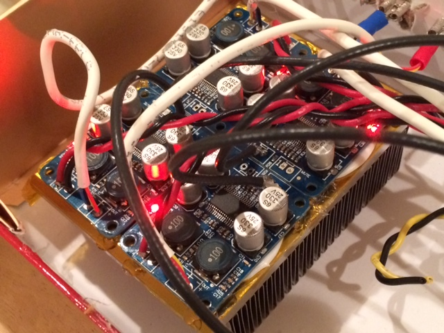
So you mounted the heat sink on the bottom of the boards? I can see that what you used is far larger than what you could ever possibly mount on top of the chips but is that effective? Will it work well enough in a real world situation as opposed to a test into a dummy load? I have pretty efficient speakers so I don't expect to ever need more than a few watts except for peaks.
The TPA3118 has a thermal pad on the bottom that is connected with solder to vias directly beneath the chip. And the PCB is supposed to be the heatsink. Normally this is enough - especially when running circa 12w to 25w as this chip was designed to do. But given that it is mounted on an exceedingly small PCB that has very little area or copper ground plane to radiate from, and we are basically driving it in a range beyond its normal design - my thought was to help remove the heat off the bottom. You could put a heatsink on the top and it would certainly help but it doesn't t have the metal pad on top.
I am just removing heat from the heat sink (the PCB).
I am just removing heat from the heat sink (the PCB).
")
http://www.diyaudio.com/forums/clas...ker-protection-eq-any-good-2.html#post4627688
Works great. $13. No thump, no BT noise.
Works great. $13. No thump, no BT noise.
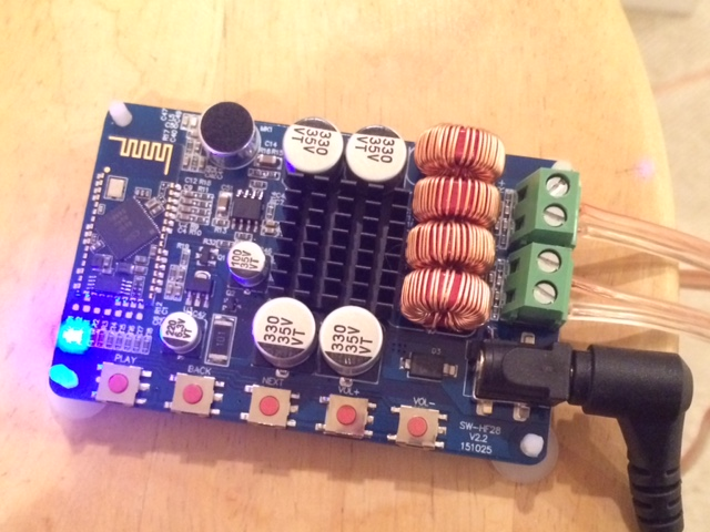
Why is the microphone ???
Надіслано від мого K00Z, використовуючи Tapatalk
The mic is the round can with the black dust protective cover at top left in the photo. It is to allow BT phones to be used as hands free speaker phones.
- Home
- Amplifiers
- Class D
- TPA3116D2 Amp