A lot of people get confused (including myself in the past). Balanced means same impedance in both send and return. But for most of us we consider balanced to also have a differential drive. But you can have balanced and single ended drive and differential but unbalanced (although that is daft).
Either way if you are selling a product you should check what it's being plugged into!
It's the differential receiver that's critical for common mode rejection. The output driving it just needs balanced impedances. Signal symmetry is irrelevant as common mode rejection works even in the absence of any signal.
ee
@Billshurv:
bottom of first page UK Google!
Kim Kaplan Productions - A One Stop Media Shop Kim Kaplan Productions
bottom of first page UK Google!
Kim Kaplan Productions - A One Stop Media Shop Kim Kaplan Productions
@Billshurv:
bottom of first page UK Google!
Kim Kaplan Productions - A One Stop Media Shop Kim Kaplan Productions
Lost me there.
It's the differential receiver that's critical for common mode rejection. The output driving it just needs balanced impedances. Signal symmetry is irrelevant as common mode rejection works even in the absence of any signal.
ee
So why is a headphone not a differential receiver? Common mode with a balanced impedance has no net movement? Or are we heading down a symantic rabbit hole?
So why is a headphone not a differential receiver? Common mode with a balanced impedance has no net movement? Or are we heading down a symantic rabbit hole?
Sure, a headphone driver is essentially a balanced, differential input. But for what purpose? You think you're going to pick up audible noise on your headphone cable? And my point was that the input of a bridged amplifier is not a differential input.
By the way, the first "balanced" amp from HeadRoom never mentioned common mode rejection. It was all about the bridging. Increased power, etc. though the increased power was irrelevant. A single ended amp can have whatever power you want.
It was just a naive misapplication of the term "balanced," but it has stuck.
se
Ah we are on the same page. But what do I know, I have Koss ESP/950s")
se
Sure, a headphone driver is essentially a balanced, differential input. But for what purpose?
Common mode rejection in the lower AM band, duh. Not that I can hear that high anymore without a radio.
Common mode rejection in the lower AM band, duh. Not that I can hear that high anymore without a radio.
What, are you deaf or something?
se
Um, no.
*sigh*
se
Thats how patent reads to me.... the + and -45 degree stuff. But, I can easily measure that affect if I had the unit to measure. SY can do it also.
Since the patent is so old.... expired now (?). we can measure and listen and see how to do IT better..... assuming it makes an audible improvement.
Anyone have the actual values used by MIT? I am more interested in the RC circuit affect than CM rejection et al which has not been a problem in my systems.
THx-RNMarsh
Last edited:
I think you're looking at the wrong one.
Historically, each interval of the chromatic scale was given a role in keeping with the presence of the church at the time. For example, the first and fifth in a scale are absolute monarchs: Without them, there can be no music.
The third, fourth and seventh intervals are aristocrats, mighty lords of harmony. Most complex and interesting harmonies are built using these “melody notes”. The second and sixth intervals are more like clergy: influential Within their proper sphere.
The remaining five tones are music’s canaille, the street mob.
No............... In the active domain bridged amplifiers are what creates balanced signals.
Balanced means balanced impedance connection. The equal or non equal voltages on the signal line have NOTHING to do with a balanced impedance connection.
it doesn't make it a balanced impedance connection.The only topological difference between this and a 5532 driving a transformer primary appears to be power delivery. In the headphone case two amplifiers drive two copper wires feeding a floating driver coil. If this isn't 'balanced' why would replacing the driver's voice coil former and magnet gap with an inductively coupled second winding suddenly make it a balanced circuit?
Bridged is quite different from balanced impedance connection.Don't get me wrong, that headphone cable is comical and save for special niche circumstances the benefits of 'balanced' headphone drive also escape me, I just don't see bridged and balanced as contradictory concepts.
What do you mean "real data"? Again, Bruce's whole premise is nonsense. How does "real data" manage to come from nonsense?
You'd be surprised what's patentable. Ray Kimber got a patent on a cable design that was patented in 1960. The patent office is just a rubber stamp. Any quack can get a patent on the craziest things.
And why is it impossible for you to simply look up Bruce's patents?
se
Also, if things weren't confusing enough, in the United States a "patent" covers other Intellectual Property that is not an invention. So, for example, what in other nations is referred to as an Industrial Design ... which covers things like the shape of an automobile, for example ... are called "Design Patents" in the US.
Shady companies imply that the Design Patent refers to a form of invention; the classic example is the Q-Ray Bracelet.
You can't make a bracelet that looks like the Q-Ray because it has a registered Design Patent. But Q-Ray in their television advertising implies that it has a patent on the function of a "healing bracelet".
It seems that Design Patents are ideal for the Cable "industry". I'm surprised they haven't jumped on that one yet.
Brisson's application is for a utility patent. He's managed to keep the application alive for nearly ten years now. The fact that his attorney is Timothy Brisson is, I'm sure, just a coincidence.
I haven't read the file wrapper, but I'd guess that it's highly entertaining.
I haven't read the file wrapper, but I'd guess that it's highly entertaining.
Brisson's application is for a utility patent. He's managed to keep the application alive for nearly ten years now. The fact that his attorney is Timothy Brisson is, I'm sure, just a coincidence.
I haven't read the file wrapper, but I'd guess that it's highly entertaining.
Tim is, of course, Bruce's son.
If you can add value or 'improvement' or other modification to the patent, you could keep extending the application and/or patents life.
Still, the patent is about the Network. Does anyone know the values he used in that network?
THx-RNMarsh
Not specified as a preferred embodiment, which is unlikely to fly if they ever want it to be issued. One claim, and it looks completely meaningless. It appears to be a "show" patent rather than a serious one. That's viable if you have a cheap or free lawyer.
I love Roger Modjeski's comments in his BAF talk.
I love Roger Modjeski's comments in his BAF talk.
Finally. Some one will be able to tell me what the circuit consists of and real data.
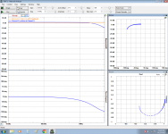
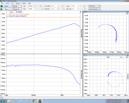
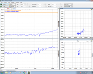
Here you go. Far less here than meets the eye. The titles should be self explanatory. Data taken with 300R load on the headphone end. 1V magnitude. The dominant effect is merely the capacitance of the cable.
edit: 50R source impedance.
Attachments
Here you go. Far less here than meets the eye. The titles should be self explanatory. Data taken with 300R load on the headphone end. 1V magnitude. The dominant effect is merely the capacitance of the cable.
edit: 50R source impedance.
se
Here you go. Far less here than meets the eye. The titles should be self explanatory. Data taken with 300R load on the headphone end. 1V magnitude. The dominant effect is merely the capacitance of the cable.
edit: 50R source impedance.
Ok now pls add a simulated headphone circuit for a load -- some L and HF resonance. Then do the group delay of it at load.
It also seems to be like the RC network used at speaker end which reduces ringing etal.
THx-RNMarsh
Last edited:
- Status
- This old topic is closed. If you want to reopen this topic, contact a moderator using the "Report Post" button.
- Home
- Amplifiers
- Headphone Systems
- This is what happens...