It is different from last schematic which is:
I used it to recreate the asc file but the regulator reduce from 0.0001V to 0.0020V ? I attached my asc file with the post.
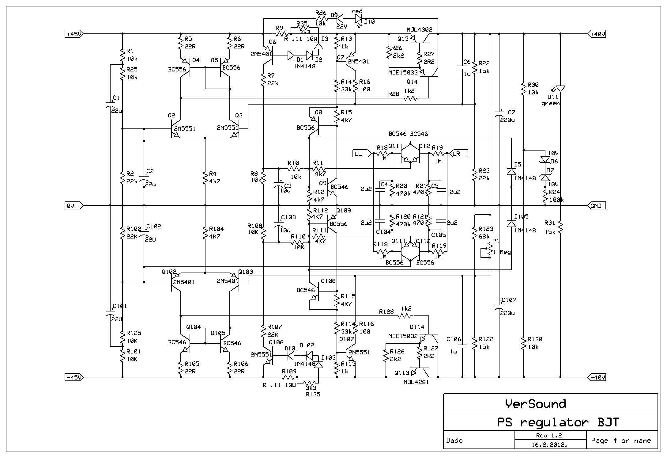
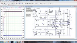
I don't think it's different. You used wrong R123 value, it should be 68k parallel with 1 Mega trimer not 22k. Just use .asc file I've sent. It should looks as attached picture.
Attachments
Thanks! I found my problem which is R123 should look like yours and must connect to R23. After changed, anything worked like it should be.
I asked because the new schematic have the same part names as the pcb.
And it seem that trimpot P1 was used to change the output voltage.
I asked because the new schematic have the same part names as the pcb.
And it seem that trimpot P1 was used to change the output voltage.
Thanks! I found my problem which is R123 should look like yours and must connect to R23. After changed, anything worked like it should be.
I asked because the new schematic have the same part names as the pcb.
And it seem that trimpot P1 was used to change the output voltage.
Whit that trimpot you adjust negative output voltage to be equal to the positive output voltage.
How big heat-sink need for the PSU Regulator since I want to use separate heat sink? I only know that my amp need max 7A so it is ~ 50W power spent in the regulator.
This is the max power, normal listening power is much lower, you dont need to big heat sink. I am out of my house (a kind of vacation, I am retired so no more real vacation) and with my tablet only with no possibility to simulate.
TT amp with EC
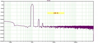
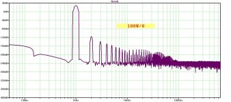
I could not to resist to try simulate this TT amp with the Error Correction circuit by Sergio (smms). I did some improvement and simplification (DN2535 replaced with a resistor).
Simulation results are impressive (it will need some more improvement in GM).
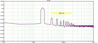
THD20 is just 1 ppm at 50W/8 ohm, and THD1 is 0.04 ppm at 50W/8 ohm. At 1W both THDs are vanishing low.
BR Damir
I could not to resist to try simulate this TT amp with the Error Correction circuit by Sergio (smms). I did some improvement and simplification (DN2535 replaced with a resistor).
Simulation results are impressive (it will need some more improvement in GM).
THD20 is just 1 ppm at 50W/8 ohm, and THD1 is 0.04 ppm at 50W/8 ohm. At 1W both THDs are vanishing low.
BR Damir
Attachments
very good.
try without the jfet/DN2535 buffer , and put the c29/R63 in parallel with the error resistor to increase the open loop phase margin.
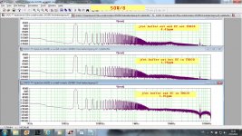
Phase Margin lost completely with RC (C29/R63) parallel to the error resistor, so I put it back as shunt compensation, but without jfet/DN2540 phase margin improved a bit and the gain margin improved a lot.
Interesting thing is that the distortion did not suffered a lot without jfet buffer, THD1k increased from 0.04 ppm to 0.05 ppm and THD20k from 1.01 ppm to 1.29ppm.
Most interesting thing is that even without the EC distortion of this amp is very very low and EC did not lower so much distortion as it improved distortion harmonic distribution, by killing nasty OPS distortion.
I see it as the main gain here.
BR Damir
ps. Sergio how do you explain that removing the jfet buffer did not influenced to much functioning the EC, as this EC asks for low source impedance? I would explain that with the VAS output impedance falls with a frequency and those the EC works better at higher frequencies.
Attachments
Last edited:
is strange that the phase margin don't improve with the EC compensation as I advice,
you have to change the miller capacitor value or increase R10/R11 (did you try that?).
The error correction only affect the output stage, and can only diminish distortion created in the output stage, It means that if you want even lower distortion you have to change your input stage, but I do not see the need as your distortion is already very low, and as you said the nasty crossover distortions are improved thanks to the EC.
You dont need the jfet buffer because The output of the VAS stage is only high impedance in open loop, inside a feedback loop the output impedance of the VAS is very low.
PS: Try making the same THD test with lower load resistor like 2R , the differences of the EC vs no EC should be more visible at difficult loads.
Last edited:
is strange that the phase margin don't improve with the EC compensation as I advice,
you have to change the miller capacitor value or increase R10/R11 (did you try that?).
The error correction only affect the output stage, and can only diminish distortion created in the output stage, It means that if you want even lower distortion you have to change your input stage, but I do not see the need as your distortion is already very low, and as you said the nasty crossover distortions are improved thanks to the EC.
You dont need the jfet buffer because The output of the VAS stage is only high impedance in open loop, inside a feedback loop the output impedance of the VAS is very low.
PS: Try making the same THD test with lower load resistor like 2R , the differences of the EC vs no EC should be more visible at difficult loads.
Sorry for delayed response, I have to look after my grandson those two weeks and no much time for my hobbies left.
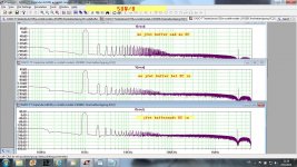
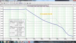
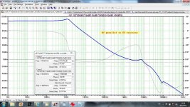
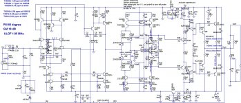
I was, probably, not clear with my explanation about shunt compensation after the EC and the compensation parallel to the EC resistor. The PM really improved but a peak showed at about 8MHz and GM was practically not existent. I tried to increase the LTP source resistors( from 18R to 100R) and that improved a bit but not enough, any capacitive load make the amp unstable. I tried to manipulate the TMC and came close, but final result never reached the shunt compensation.
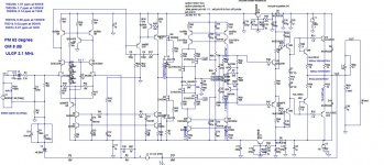
Attached, last schematic, LG of that, and LG with the compensation parallel to the EC resistor to demonstrate what I mean.
The lower load of 2 ohm really shows the effectiveness of the EC. THD20k for 8 ohm was improved from (EC off) 4.41 ppm to (EC on) 1.29 ppm and for 2 ohm from 8.47 ppm to 1.53 ppm.
BR Damir
Attachments
Last edited:
smm73 ... have you studied amplifier topologies with separate feedback on the input circuits, plus separate feedback on the output circuits??
======
Aggressive local output stage feedback reminds me of the thread on Dan D'Agostino's Momentum amp, as well as recent threads on philosophies on how to voice an amplifier. Feedback is one tool for "voicing".
http://www.diyaudio.com/forums/soli...ke-pure-classa-se-despite-low-idle-power.html
========
"In the interview Dan D' Agostino talks about a low feedback design with only 8-10 dB overall feedback, but local feedback around the output devices that need heavier feedback to perform well...sounds a bit like two split feedback loops."
From what I have read, Dan's Momentum amp does not have global feedback from the output to the input, but it does have (patented) nested feedback over the input stages plus (large amounts of) error correction feedback on the output stage.
The Momentum design goal appears to focus on isolating output noise from the high sensitivity diff input. To me, this is the most interesting discussion point.
1) The reverse currents from high inductance speaker voice coils can affect the sound if they are fed back to the high gain differential input stage.
2) All Krell amp schematics I have seen use MOSFETs for the first output driver stage, with the goal of isolating the speaker's reverse currents from the gain stages. I do not know if the Momentum design includes this voltage-to-current isolation. John Curl's amps also use a MOSFET output driver for this same isolation goal.
3) RFI noise, especially from digital Wi-Fi networks and in-home local networks, can get picked up on the speaker interconnect cables and fed back to the high gain differential input stage.
4) Nested feedback over the high frequency, low capacitance input stages is more accurate than global feedback that goes around the lower Ft 24-pair output stage. Very little noise gets injected into the intput stage loops.
Sorry for delayed response, I have to look after my grandson those two weeks and no much time for my hobbies left.
I was, probably, not clear with my explanation about shunt compensation after the EC and the compensation parallel to the EC resistor. The PM really improved but a peak showed at about 8MHz and GM was practically not existent. I tried to increase the LTP source resistors( from 18R to 100R) and that improved a bit but not enough, any capacitive load make the amp unstable. I tried to manipulate the TMC and came close, but final result never reached the shunt compensation.
Attached, last schematic, LG of that, and LG with the compensation parallel to the EC resistor to demonstrate what I mean.
The lower load of 2 ohm really shows the effectiveness of the EC. THD20k for 8 ohm was improved from (EC off) 4.41 ppm to (EC on) 1.29 ppm and for 2 ohm from 8.47 ppm to 1.53 ppm.
BR Damir
Same situation here, my 9 moths son takes all my free time... but I can not resist That peak can be due to the mje15032/33 driver transistors, 220p and the base resistors seems low, try to increase for at least 10R and 660p. I have a circuit that is similar to yours, but different input, and it does not have that problem.
I like the way you bootstrap the input jfet.
LineSource the amplifier that I am designing have the output stage completely separate from the input stage, it is essentially a current amplifier without no voltage amplification, it will be built on a separate box from the input voltage stage. will use a combination of error correction and feedback, and is very linear and fast.
I also believe that using fast local loops are much better than a slow global loop, and ofcourse the isolation of the back EMF from speakers, but there is other factors that I think is very important like the noises in the output stage powers supply and ground loops that can have a negative impact on the input stage.
using mosfets as drivers is a good option, but a triple output stage also have a very high input impedance, so I think this is more a matter of taste. I like mosfets ... but also like transistors.
Have to take a look to the momentum.
I also believe that using fast local loops are much better than a slow global loop, and ofcourse the isolation of the back EMF from speakers, but there is other factors that I think is very important like the noises in the output stage powers supply and ground loops that can have a negative impact on the input stage.
using mosfets as drivers is a good option, but a triple output stage also have a very high input impedance, so I think this is more a matter of taste. I like mosfets
... but also like transistors.Have to take a look to the momentum.
Also, where did that EC circuit originate? It's very concise, although a bit sensitive to operating point and component values.
That EC circuit was design by me two years ago, but find out some months ago that dr. Malcolm Hawksford has presented a paper in 1983 that also use a complementary differential pair to perform error correction , but the Hawksford circuit does current and voltage correction of the output stage. A similar situation of yours Kuartlotron circuit
.
Last edited:
Kean, you are right, the corner frequency is to high(1.6 GHz) to have any influence on the gain margin, that is what I tried to improve. The best is to put just 6.8 pF with no resistor and than the PM is 68 degree and the GM is 15 dB.What is R67 in the feedback network for? What is the corner frequency of a 10p+10R series network?
The Momentum design goal appears to focus on isolating output noise from the high sensitivity diff input. To me, this is the most interesting discussion point.
If you isolate the output errors from the LTP, then the LTP can't correct them. So unless there is an alternate feedback loop, it is counterproductive.
1) The reverse currents from high inductance speaker voice coils can affect the sound if they are fed back to the high gain differential input stage.
This "isolation" roughly translates into an amplifier with low emulated output inductance. Imagine a lossy nonlinear inductor at the output of your amplifier that changes value during crossover and at excursions. Mfet drivers and EF3s reduce this.
3) RFI noise, especially from digital Wi-Fi networks and in-home local networks, can get picked up on the speaker interconnect cables and fed back to the high gain differential input stage.
Isn't the same true for the input cables? And the power cord? And how do we know that nested feedback makes this better? What if it makes it worse? Data?
4) Nested feedback over the high frequency, low capacitance input stages is more accurate than global feedback that goes around the lower Ft 24-pair output stage. Very little noise gets injected into the intput stage loops.
What do you mean by "accurate"? The THD of that amp is quite high.
Last edited:
- Status
- This old topic is closed. If you want to reopen this topic, contact a moderator using the "Report Post" button.
- Home
- Amplifiers
- Solid State
- ThermalTrak+TMC amp