Thanks Mr.,so it's suitable for an 100w RMS amplifier ...Hi Thimios
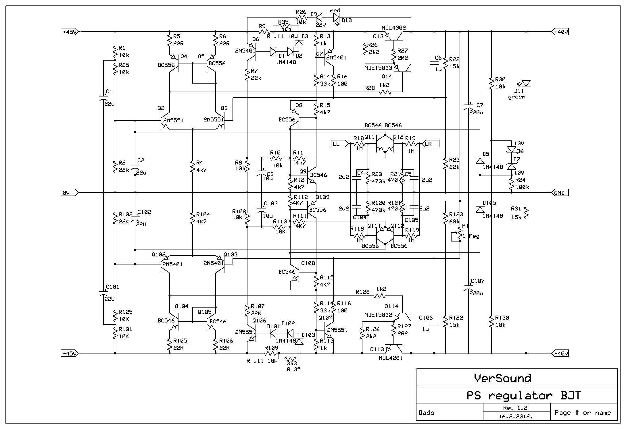
As showed in the schematic, about 12 A, the current sensing resistors R9 and R109 are made from two parallel 0.22R 5 W resistors. The trick is that that the max current is a transient dependent, shorter the current pulse higher is the current trigger point. If I remember correctly my simulation(it was two years ago) the trigger point varies from 10 to 15 A, higher for shorter pulse. As the voltage drop on the serial transistor is about 6 V, it's easy to calculate dissipated power on that transistor at different currents. Average power dissipation in the PS regulator is quite low, except if listening rock music very loud prolong period.
Current limit could be easily changed by changing the value of the sensing current resistors.
BR Damir
It's not a rumor. They already are retiring the 21193/4 and also the 4281/4302 types. It's a pitty, they could've kept at least the top of the line types.
I sold quite a few NJL4281, NJL4302 in matched triplets, but not in several months.
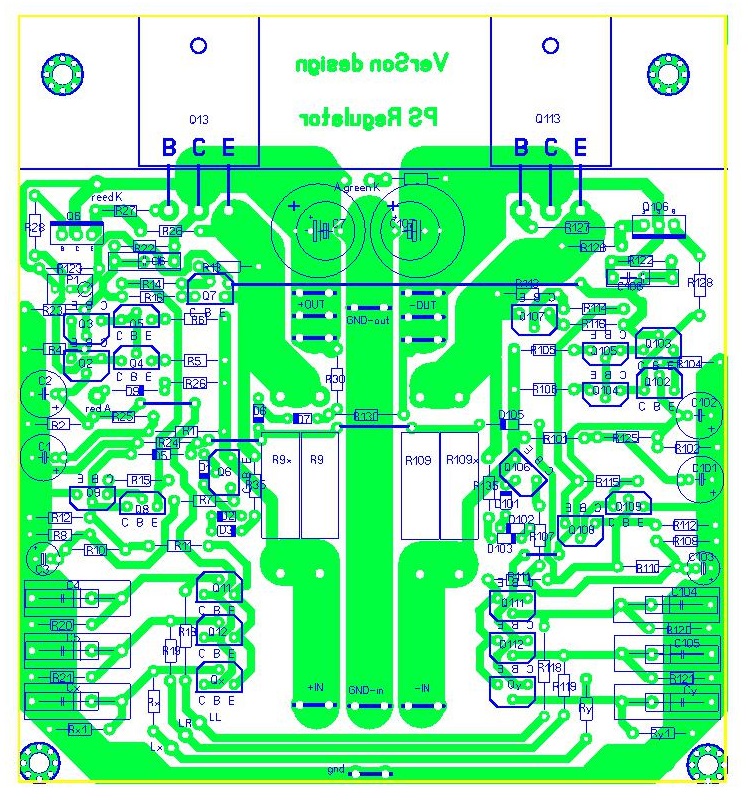
Improved version of the regulator, with correct layout.
Could you upload the component layout file for this PSU? I want to build it in my amp which use +/-54V right now. With the regulator it will be +/- 49V and still work well. Thanks!
Could you upload the component layout file for this PSU? I want to build it in my amp which use +/-54V right now. With the regulator it will be +/- 49V and still work well. Thanks!
Tell me what do you need exactly, the layout, pdf file for a transfer or photo to make the PCB, BOM?
Tell me what do you need exactly, the layout, pdf file for a transfer or photo to make the PCB, BOM?
Thanks,
I want to have the layout, pdf file for a transfer. Other thing like schematic and BOM, I already got them from this thread.
Thanks,
I want to have the layout, pdf file for a transfer. Other thing like schematic and BOM, I already got them from this thread.
OK, here it is.
Attachments
OK, here it is.
Could you upload for me a version of this image:
but with the pdf format and no track visible. I think it is called "Component Layout" but not sure if I used the right word.
Could you upload for me a version of this image:
but with the pdf format and no track visible. I think it is called "Component Layout" but not sure if I used the right word.
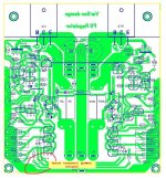
You mean this, it is called silkscreen. Mirrored image use for the transfer method.
Attachments
You mean this, it is called silkscreen. Mirrored image use for the transfer method.
Yes, this is exactly what I need. Thanks!
Yes, this is exactly what I need. Thanks!
This PS regulator was designed for my three channels amp, so if you are going to use it for a stereo(two channels) then you don't need to assemble all components with designation x and y, those are for third channels DC offset sensing.
I appreciate if you report back your result with this PS regulator.
Damir
I will do that. I have two DIY amps that I can apply the PS Regulator and compare.
I also have some questions:
- In your BOM file (in old post) - you said all resistors must be metal film 1% 0.5W --> I think it is 0.25W ? Because I check another google docs BOM in this topic and found out almost res on the list is 0.25W.
- Is it ok to use KOA / BC resistor type on this PS Regulator? Any improve if I use Dale?
Yes, you can use KOA / BC resistor type 0.25 W, except 5 W wire wound sensing resistors.
I don't think Dale will improve, keep those for important positions in an amp.
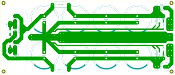
I'd like to use your PSU design, too. But too bad, my big caps won't fit it. SO I goes through a hard way and try to copy your layout to make it fit my cap (is it ok)? I will use 4 x 10000uf / 63V in each pos and neg rail.
But in your PSU, I found a strange resistor after the big 20000uf (not in schematic)? I think it is bleeder resistor? And I calculate it for 10ma -> ~5K. Is it right?
I also run the LTSpice with the PU regulator (55V input), all caps seem only need < 50V rating base on voltage on both lead?
After that. I will make the board and try to fetch components on the same time.
Attachments
Last edited:
I'd like to use your PSU design, too. But too bad, my big caps won't fit it. SO I goes through a hard way and try to copy your layout to make it fit my cap (is it ok)? I will use 4 x 10000uf / 63V in each pos and neg rail.
But in your PSU, I found a strange resistor after the big 20000uf (not in schematic)? I think it is bleeder resistor? And I calculate it for 10ma -> ~5K. Is it right?
After that. I will make the board and try to fetch components on the same time.
Yes, you've got it all correctly, just use 1 W bleeder resistor.
Just one more thing, when you test the PS regulator use external bleeder resistors of, let's say, 500 ohm 10 W, PS regulator won't show correct values with no load. I suppose you will test the PS regulator first with no amp connected.
Yes, you've got it all correctly, just use 1 W bleeder resistor.
Just one more thing, when you test the PS regulator use external bleeder resistors of, let's say, 500 ohm 10 W, PS regulator won't show correct values with no load. I suppose you will test the PS regulator first with no amp connected.
I have to disturb one more thing about the PS regulator layout. Could you upload for me the solder mask layer? I didn't have pcb skill so I asked some pcb company here to make it but they told me that they need that layout.
I have to disturb one more thing about the PS regulator layout. Could you upload for me the solder mask layer? I didn't have pcb skill so I asked some pcb company here to make it but they told me that they need that layout.
Here it is.
If you need gerber files PM me.
Attachments
Here it is.
If you need gerber files PM me.
Thank you! The PCB is on going now, I will post its image when receive it.
Based on another thread about this PS Regulated, you told it could:
- electronic fuse triggered with delay depend on the current level (shorter for higher currents)
- loudspeaker electronic protection
I can understand the first thing but the second thing "loudspeaker electronic protection", how is it working? Could it replace decade speaker protection function?
Thank you! The PCB is on going now, I will post its image when receive it.
Based on another thread about this PS Regulated, you told it could:
I can understand the first thing but the second thing "loudspeaker electronic protection", how is it working? Could it replace decade speaker protection function?
It protects against power amp output DC offset. In the attached PCB you can see where to connect power outputs, and in the case DC offset the PS regulator will detect it and switch off, but not on audio signals. It reacts on below 1 Hz.
I don't know what is decade speaker protection function, but you don't need any other type loudspeaker protection.
Attachments
It protects against power amp output DC offset. In the attached PCB you can see where to connect power outputs, and in the case DC offset the PS regulator will detect it and switch off, but not on audio signals. It reacts on below 1 Hz.
I don't know what is decade speaker protection function, but you don't need any other type loudspeaker protection.
ilkafrv ask me for last .asc file.
Attachments
- Status
- This old topic is closed. If you want to reopen this topic, contact a moderator using the "Report Post" button.
- Home
- Amplifiers
- Solid State
- ThermalTrak+TMC amp