show us the arithmetic to back up "is fine with sure".for 50vac transformer 80v capacitors is fine with sure
a 5% regulation 230:50+50Vac transformer run from maximum tolerance UK mains supply will give ~+-81.5Vdc after the bridge rectifier.
DC = Vsupply / Vratedprim * Vratedsec * (1+regulation) *sqrt(2) -0.5 ~
254/230*50*1.05*1.414 - 0.5 = 81.48Vdc
6% regulation gives 82.26Vdc, 4% regulation gives 80.7Vdc.
Then each builder can check their own voltages before they buy the wrong components.
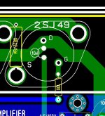
..... I think it's ok with terminal assigment look at the picture below .
Source resistors are on bottom side optional .")
Alex.
Alex. Maybe I am completely wrong. But are you shure drain and gate should not be the other way round? But off course my memory could be mistaken. It was some 15 years since I dealed with these (SJ 50, SK135)
I have been playing with every variant of this goldmund all the way up to the "enhanced version".. and with this one .... my ??? is .... where is the bias adjustment ?? Maybe some magical autobias circuit??
With different model laterals (hitachi , exicon , renesis) the circuit had to be adjusted to define my 100mA Xover point , why not "allow this" on a clone ??
OS
Maybe some magical autobias circuit?? With different model laterals (hitachi , exicon , renesis) the circuit had to be adjusted to define my 100mA Xover point , why not "allow this" on a clone ??
OS
Please take a look at the attach spec for ECF10N20. Alex is right with the pcb.
Alex, do you think you can send me the Sprint file? Tks.
Please don't keep asking about the source resistor. Post 1067 has shown how we can implement them even w/o changing the pcb. Alex had even changed it to show everything. But Alex, we still have to insulated the top screw as I had shown in Post 1067 right? My photo was a bit different from alex's drawing because I had a different orientation of the TO-3 (that was my super leach 8xTO-3), but the idea stands. Everybody is happy with the source resistor now?
I have been playing with every variant of this goldmund all the way up to the "enhanced version".. and with this one .... my ??? is .... where is the bias adjustment ??
With different model laterals (hitachi , exicon , renesis) the circuit had to be adjusted to define my 100mA Xover point , why not "allow this" on a clone ??
OS
It either shows a total lack of understanding of how to build a amp or a total lack of consideration for other people planning on building this thing, who may not be that experienced.
forget to attach. here it is again.
On the data sheet it is viewed from the under side. Alex drawing seems to be seen from above. Maybe I am still wrong. But it does not look right to me. Sorry for bothering and maybe my brain is confused today...
On my old PCB it looked like this anyway seen from above:
Attachments
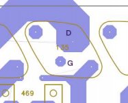
Try to do it this way :
The line between G & D and the line between the 2 mounting screws makes a cross (not a +), the G is on the left when looking from top. Your drawing is right and so is alex's. the orientation of your drawing is confusing you. If you rotate your drawing to make the cross upright and do the same with alex, (angle of rotation is different for the 2 cases) you will see they are the same.
The line between G & D and the line between the 2 mounting screws makes a cross (not a +), the G is on the left when looking from top. Your drawing is right and so is alex's. the orientation of your drawing is confusing you. If you rotate your drawing to make the cross upright and do the same with alex, (angle of rotation is different for the 2 cases) you will see they are the same.
It either shows a total lack of understanding of how to build a amp or a total lack of consideration for other people planning on building this thing, who may not be that experienced.
An idle current adjust will also allow for the best sound. I know that models are just models , but each had a "sweet spot" where the THD was far lower. For some it was <100ma but others were higher. Different lots of my BJT's also will bias differently depending on their Hfe. Just common sense...
OS
"show us the arithmetic to back up "is fine with sure".
a 5% regulation 230:50+50Vac transformer run from maximum tolerance UK mains supply will give ~+-81.5Vdc after the bridge rectifier.
DC = Vsupply / Vratedprim * Vratedsec * (1+regulation) *sqrt(2) -0.5 ~
254/230*50*1.05*1.414 - 0.5 = 81.48Vdc
6% regulation gives 82.26Vdc, 4% regulation gives 80.7Vdc."
That should be but in real life even with low drop voltage rectifiers this will not be truth.
Everybody can check this easely.
By the way do you calculate regulated voltage with 60VAC transformer? Regarding your formula it will be 97,9V. Pretty close to 100V. What do you think?
"show us the arithmetic to back up "is fine with sure".
a 5% regulation 230:50+50Vac transformer run from maximum tolerance UK mains supply will give ~+-81.5Vdc after the bridge rectifier.
DC = Vsupply / Vratedprim * Vratedsec * (1+regulation) *sqrt(2) -0.5 ~
254/230*50*1.05*1.414 - 0.5 = 81.48Vdc
6% regulation gives 82.26Vdc, 4% regulation gives 80.7Vdc."
That should be but in real life even with low drop voltage rectifiers this will not be truth.
Everybody can check this easely.
By the way do you calculate regulated voltage with 60VAC transformer? Regarding your formula it will be 97,9V. Pretty close to 100V. What do you think?
In real life , my 53-0-53VAC trafo gave 78+ VDC rails with bad capacitors (4+% reg ??). With new ones , I get a rock solid 75VDC (<1% reg). With very small capacitors for testing , the same trafo read 80.5V per rail after the bridge. I derated and used 100V electrolytics just to be safe ... why not ?? The 60-0-60 would most likely give 85-88V rails.
OS
Last edited:
The point I have made is never tell builders "it will be fine", when you don't know what their operating conditions are.
Show the builders how to check it and measure it. Let them decide on whether to take the risk.
Do not accept responsibility for killing someone by remote control, due to your own negligence.
Show the builders how to check it and measure it. Let them decide on whether to take the risk.
Do not accept responsibility for killing someone by remote control, due to your own negligence.
where is the arithmetic?"show us the arithmetic to back up "is fine with sure"...............
.................By the way do you calculate regulated voltage with 60VAC transformer? Regarding your formula it will be 97,9V. Pretty close to 100V. What do you think?
What are the operating conditions you have assumed?
How can a builder with little experience check if your assumptions meet his operating criteria?
You should have quoted:
a 230:60+60Vac 5% regulation transformer on a 254Vac supply will give ~97.9Vdc
I can confirm your arithmetic seems to be correct, but I had to make a number of assumptions for what you had used to determine the modeled DC voltage.
Try to do it this way :
The line between G & D and the line between the 2 mounting screws makes a cross (not a +), the G is on the left when looking from top. Your drawing is right and so is alex's. the orientation of your drawing is confusing you. If you rotate your drawing to make the cross upright and do the same with alex, (angle of rotation is different for the 2 cases) you will see they are the same.
Right, I did not notice the position of the drilling holes at first. Sorry for bothering.
PDF files for PCB ...
..... files for top , bottom and silk screen in attachaments in PDF format .
I will send files in LAY. format to bigpanda .
Alex.
..... files for top , bottom and silk screen in attachaments in PDF format
.I will send files in LAY. format to bigpanda .
Alex.
Attachments
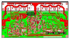
The layout is finished. Anyone who wants to place a last minute order for the group buy, please go here and follow instructions in post #6: http://www.diyaudio.com/forums/group-buys/175296-pcb-order-goldmun-clone-18.html#post2353781
Please ignore the part regarding the protection circuit boards, as everything has now been incorporated into the main board. You'll need 2 boards (1 pair) in order to build a stereo amplifier. Once we get the boards, I'll start a brand new thread and everyone can follow while I build the amplifier step by step. I will list all the parts that I decide to use, sources where I got them from, and any minor tweaks/changes that I incorporate.
Please ignore the part regarding the protection circuit boards, as everything has now been incorporated into the main board. You'll need 2 boards (1 pair) in order to build a stereo amplifier. Once we get the boards, I'll start a brand new thread and everyone can follow while I build the amplifier step by step. I will list all the parts that I decide to use, sources where I got them from, and any minor tweaks/changes that I incorporate.
- Home
- Amplifiers
- Solid State
- The Very Best Amplifier I Have Ever Heard!!!!